�� S I
M U L A T O R M A N U A L
� for Cry Engine 3
Free SDK
by Chris Wright
chris.wright1777@gmail.com
March 2019
INTRODUCTION
This is a free simulator designed to run on Cry Engine 3 (the Free SDK).
It is entirely programmed in Lua, a high performance scripting language highly
integrated into Cry Engine. Its architecture is completely open and documented,
so that users can easily create new vehicles or scenery for it. Using the
add-on libraries feature in Aircraft Factory, users can create custom Lua code
to change or add new features.
The main features of the simulator are as follows:
o Wide range of vehicles: aircraft, trains, ground vehicles
(e.g. cars, trucks, tanks), ships, submarines and spacecraft.
o All vehicles fully flyable or drivable by the player.
o Aircraft Factory, a program that automatically creates the Lua code for all
vehicle types and allows users to create new vehicles. Aircraft Factory is
included with the simulator.
o Full combat. Vehicle weapons include machine guns and cannon, bombs, guided
and unguided missiles, and vehicle gun positions / turrets.
o Advanced vehicle AI system, including combat, following waypoints and
executing waypoint commands.
o Simulator editor can be used to create and edit waypoints, rail tracks,
roads, vehicle lights, ground lights and autogen objects.
o Dynamic fire system. The CL-215 water bomber can be used to put out fires by
dropping water bombs.
o Drivable train system. Vehicles can be shunted to form trains. Trains can
switch onto branch tracks.
o Spaceflight system. Spacecraft can be flown from the surface of the Earth to
any planet in the solar system.
o Vehicle attachment system allows aircraft to land and operate on fully
functional moving aircraft carriers, or for AI cars to drive onto a ferry which
will then carry them for a sea voyage. Vehicles can also drive into the hold of
an aircraft (e.g. the Hercules) and be taken for a flight before driving off
again.
o AI aircraft parachute drops. Vehicles previously driven aboard an aircraft
can be dropped as cargo.
o Player can realistically walk around the interiors of moving vehicles e.g.
the Constellation passenger cabin or the decks of the Titanic. Player can walk
from one carriage to the next in a moving train.
o Autogen places scenery objects (e.g. houses and trees) over wide areas or
along railtracks and roads.
o Autogen AI trains and traffic placed along railtracks and roads.
o Dynamic weather includes winds, turbulence, fog, rain and snow.
o World system creates scenery covering the entire world based on landclass
data. It supports generic terrain types (e.g. green fields or cities) and also
detailed specific scenery areas (e.g. Heathrow Airport).
Simulator Entities
The simulator system includes a number of Lua entities, as follows:
1. Vehicles e.g. aircraft, ships, trains, spacecraft etc. The Lua code
for each vehicle type is automatically created by Aircraft Factory (included
with the simulator).
2. AircraftControl
This entity provides a number of
global simulator functions which are defined by its Properties settings:
1. DLL. This specifies whether
Lua entities in the map should use the custom DLL functions. If a free SDK
version is being used which does not have a custom DLL, then the DLL settings
should be disabled, and all Lua entities must have the appropriate flow graph
loaded.
2. GPS. For real world maps,
indicates the GPS scales and offsets to be used for latitude and longitude
calculations.
3. Labels. Enables and
specifies labels which will be displayed on all or specified Lua vehicles.
4. Scenarios. Controls the
saving and loading of scenario files.
5. Vehicle slewing.
6. Tutorials and in-game help.
7. Defines the default startup
mode for vehicle controls and the HUD.
3. Editor. The simulator editor can be used to create and edit
waypoints, rail tracks, roads, autogen objects, ground lights and vehicle
lights.
4. Lights. Places static and moving lights on the terrain, e.g.
runway lights. The lights are dynamically scaled to give visibility over large
distances.
5. Weather. Dynamically controls fog, places clouds and sets snow,
rain, winds and turbulence according to location in the map.
6. ObjectsControl. Controls the main autogen system.
7. ObjectsSpawner. 25 instances of this entity are spawned in-game
and moved by the ObjectsControl entity, depending on the location of the
player. Each ObjectsSpawner entity fills a 5 km square with objects centred on
its location.
8. RailtrackObjects. Controls the railtrack and road autogen.
9. Points. Simulates railtrack points, allowing trains to switch between
main and branch tracks.
10. LevelCrossing. A level crossing that will automatically close when a
train approaches. When closed it will also stop AI road traffic.
11. SolarSystem. This entity controls the positions, offsets and scaling
of all planets and moons in the solar system.
12. Planet. Each planet and moon in the solar system is an instance of
this entity.
13. Terrain. This entity controls the detailed planetary surface which
is linked to a specified planet or moon.
World system entities:
14. TerrainControl. This entity controls the placing of terrain grids
and objects around the world.
15. TerrainSpawner. Each instance of this entity loads one terrain grid
(14000 * 7 km) and any required shorelines.
16. GridObjectsSpawner. Each instance of this entity contains scenery
objects (e.g. houses and trees) for one terrain grid.
The simulator includes a custom Game DLL (created by Tataru). It gives many
significant enhancements. For example, mouse panning is unlimited (using the
Mouse flow graph, panning will stop when the mouse cursor reaches the edge of
the screen). One nice advantage of the DLL is that the flow graph for every Lua
vehicle is no longer needed. Simply drag an aircraft onto the map and it's
instantly usable, no need to find and load the right flow graph.
CONTENTS
1. INSTALLATION
2. DEMO MAPS
3. BASIC OPERATIONS:
LOADING AN AIRCRAFT INTO A NEW
MAP
ENTERING AND FLYING AN AIRCRAFT
4.
FLIGHT CONTROL MODES
PRESETS
CAMERA VIEWS
JOYSTICK CONTROLS
PLAYER STATIONS AND WALK MODE
AIRCRAFT SCALING
DRAWING MODE
PROPERTIES SETTINGS
USING THE AI FUNCTIONS
PROPERTIES SETTINGS
WAYPOINT FILE FORMAT
WAYPOINT COMMANDS
VEHICLE ATTACHMENT (CARGO)
SAVING AND LOADING GAMES
AIRCRAFTCONTROL ENTITY
LABELS AND VEHICLE INFORMATION
HUD
COMBAT
TRAINS
SHIPS
HELICOPTERS
VTOL
SPACEFLIGHT
GROUND VEHICLES
AUTOGEN
GENERAL AUTOGEN
RAIL TRACK AUTOGEN
ROADS
WEATHER
THE
WALKER ENTITY
5. S I M U L A T O R E D I T O R
PLACING THE EDITOR IN A MAP
EDITOR SETUP
USING THE EDITOR
EDITING WAYPOINTS
EDITING RAIL TRACKS
RAIL TRACK TUTORIAL
EDITING AUTOGEN OBJECTS
EDITING VEHICLE LIGHTS
����������� 6. WORLD
SYSTEM
7. KEYBOARD AND MOUSE CONTROLS
LISTED BY FUNCTION
Simulator
INSTALLATION
1 Double-click on the Simulator.zip file to run WinZip. Before unzipping, check
that Use Folders is ticked.
2. Select all the files listed in WinZip. If you don't explicitly select any files
after opening WinZip then all files are selected by default.
3. Extract all files into the main Free SDK directory (i.e. navigate to the
Free SDK directory e.g. F:\CE358). Ensure that *all* files are selected and Use
Folders is enabled before unzipping.
IMPORTANT: do NOT extract into the GameSDK directory!
A new directory named Data will be created inside GameSDK. The demo maps
will be placed inside GameSDK\Levels.
A new directory named Simulator will be created inside the main free SDK
directory. It contains the manual, readme and the Aircraft Factory
installation.
4. After extracting the files, check that the directory
GameSDK\Scripts\Entities\Aircraft exists inside the main free SDK directory,
and that it contains a collection of Lua aircraft scripts such as
Constellation.lua. Also check that the Data directory has been created inside
GameSDK.
If you want to use the Titanic, you'll need to download and install the
models from Cryengine.com:
http://www.cryengine.com/community/downloads.php?view=detail&category=47&df_id=4501
Place the file zz_titanic_final_assets.pak in GameSDK
After installing the simulator, simply run Sandbox as normal and
load one of the supplied demo maps in the SimulatorDemo section.
When using the simulator, carrying a rifle isn't appropriate. You can
edit the default weapon by selecting Game -> Edit Equipment-Packs.... from
the top Sandbox menu. If you place No Weapon at the top of the list, you will
not be carrying a weapon. You can still select the available weapons by
pressing key 1 in normal game mode.
RUNNING THE FIRST DEMO MAP
The main demo map is named Seattle. It includes real-world
terrain/textures for an area including Seattle that is more than 100 km across.
To load the map, click on File on the top menu and then select Open....
Click on SimulatorDemo to open the demo maps and select the map named
Seattle. When it has loaded you will see a Spitfire and a collection of other
aircraft.
Press CTRL-G for game mode. You are automatically placed in walk mode
controlled by the Walker entity. Move the mouse to pan your view and press the
LH mouse button to walk forwards.
Walk controls: Press LH and RH mouse buttons to walk forwards and
backwards.
Roll the mouse wheel to adjust your height.
Press the middle mouse button to select walk speed.
To enter an aircraft, simply walk up to it and, when the prompt message
shows, press F to enter. You will be placed in the cockpit. Press F6 for an
external view. For more details on using aircraft and other vehicle types, see
below.
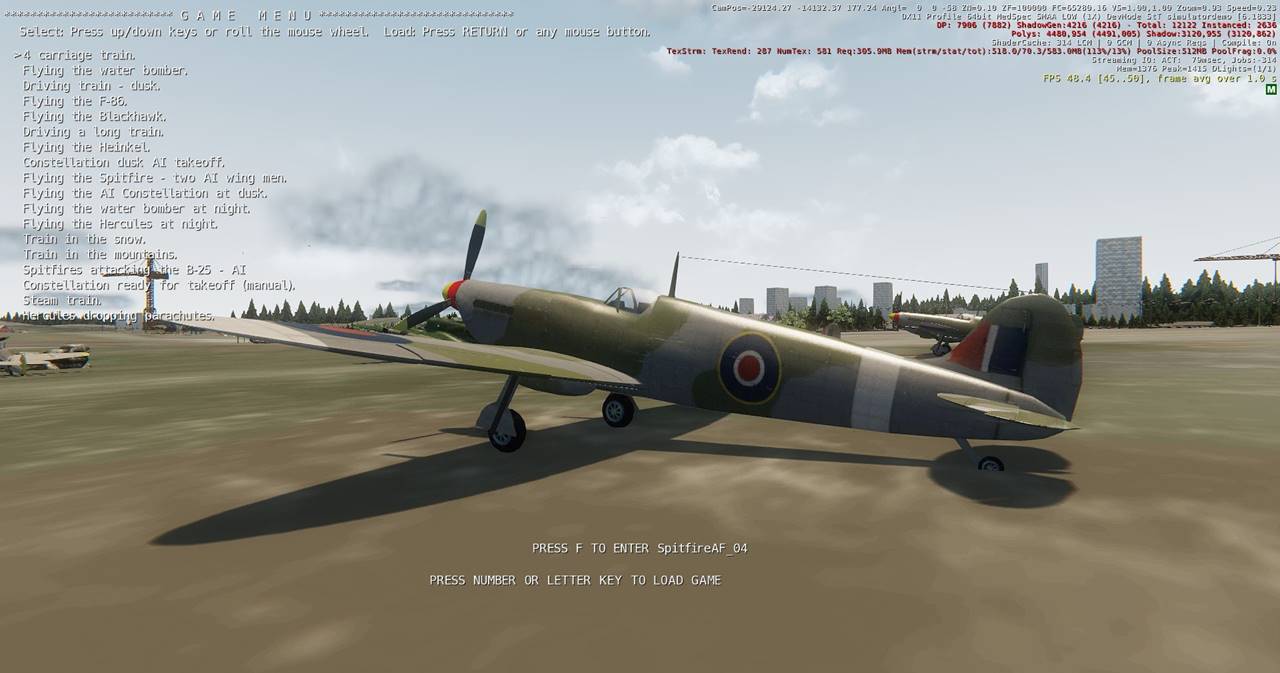
The Seattle map (and many other demo maps) has a selection of saved
games which you can immediately run:
1. In game mode, press the Backspace key. You will see a list of saved games.
The selected game is indicated by a cursor (the > character).
2. To select a game, move the cursor up/down by pressing the up/down arrow keys
or by rolling the mouse wheel. You can also move up or down ten lines at a time
by pressing the left and right arrow keys.
3. To load the selected game, press the Return key or press any mouse button.
The first game in the list will place you in a four carriage train.
For more information on the demo maps, refer to the readme.
TUTORIAL MAPS
Several real-time tutorial maps are included to help you get started.
Instructions will appear at the top left hand of the screen. When you complete
each section by pressing a command key as prompted, the text will change ready
for the next section, and so on. The first Constellation tutorial should
provide enough detail to get you into the air without reading the rest of the
manual. Another tutorial map named Training will get you up to speed on trains.
1. After loading Sandbox, click File -> Open....
Open the SimulatorDemo section and select the map named
Tutorial_Constellation.
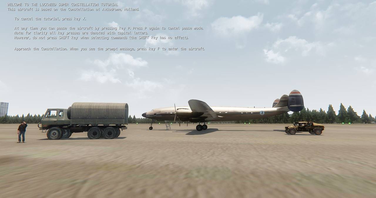
When the map opens you will see the Constellation directly in front of
you.
2. Press CTRL-G for game mode. You will now see the tutorial text, beginning
"WELCOME TO THE SUPER CONSTELLATION TUTORIAL...."
Simply follow the instructions and, before you know it, you will be a
seasoned Constellation captain!
Note: to disable the tutorial, open the objects list window and select the
entity named 'AircraftControl1'. In its Properties rollup you will see an item
named Tutorial, with the check box enabled. Simply disable (un-check) the tick
box and the tutorial text will not appear. To make this change permanent, save
the map.
BASIC OPERATIONS
LOADING AN AIRCRAFT INTO A NEW
MAP
1. If not already done so, load an instance of the Camera entity into the map
(in the rollup click Misc, then click Camera and move the mouse pointer into
the perspective window).
2. From the Entities rollup (usually on the right-hand side of the Sandbox
screen), select Aircraft and then the chosen aircraft. Drag it onto the terrain
in the perspective window. For other vehicle types, open the Trains,
GroundVehicles or Ships sections.
3. Load one instance of the AircraftControl entity into the map. Set the DLL
Properties settings as required (if the custom DLL is installed, check all
three DLL settings).
You can now enter and fly the aircraft.
ENTERING AND FLYING AN
AIRCRAFT
Note: when entering key commands, do not press the SHIFT key.
1. Press CTRL-G to start game mode in Sandbox.
2. Approach an aircraft or any other simulator vehicle. When you're close
enough to enter it you will see a message prompting you to press the F key.
3. Press the F key. You are now in the aircraft cockpit.
You can select the main views with the function keys:
Cockpit, mouse flight control: F1
Cockpit, mouse view panning: F2
External view: F6
Flyby view: F7
You can also toggle the view modes with the space bar.
4. Type in CTRL-E to start all the engines . You can also start engines
individually e.g. E1 to start engine 1 etc
5. Press F to put the flaps down.
6. Press F1 to place yourself in the cockpit with mouse flight control. Even if
you're already in the cockpit, F1 has another useful function: it places the
aileron and elevator controls in neutral (zero angle).
7. Press the RH mouse button (or the plus key) to increase throttle. The
aircraft will start to roll forward. Press the LH mouse button (or the minus
key) to reduce throttle.
8. Increase throttle to about 80% (the thrust indication at the bottom of the
screen is the percentage of maximum). At a typical speed of 100 mph the
aircraft will lift off.
9. Press F and G to put up the flaps and gear. Press the LH mouse button to
reduce the throttle to about 50%.
10. Move the mouse for flight control. As the saying goes, move the mouse
forwards to make the houses get bigger.
Move the mouse left or right to bank and start a turn. Be warned: steep
turns can bleed off air speed, so be ready to hit the throttles.
A complete list of key commands is given at the end of this manual. You can
also get in-game help by pressing the ? key.
Note: Normally, if you approach an aircraft and press F, you will be placed in
the cockpit. But there is an exception to this. Some aircraft and ships (e.g.
the Hercules, aircraft carrier and Titanic) have a defined internal volume. In
the case of the Hercules, it defines the volume of the cargo hold where cargo
can be placed.
If you approach a vehicle that has a defined volume and you enter the
volume, and then press F, you will enter the vehicle as usual, but you will be
placed in walk mode at the same location. If you place yourself near the deck
of the Titanic and press F, you will instantly be able to walk around the
Titanic. Press F1 to go to the bridge to control the ship (e.g. start engines
and drive her) and press F3 to return to walk mode.
Another example: the Hercules. Start game mode close to the Hercules.
Walk up to the rear doors. When the press F to enter message shows, press key D
(for Doors) to open the cargo doors. You can then walk into the cargo hold.
When you press F you will enter the Hercules, but you will be placed in walk
mode inside the cargo hold and at the same position. You can walk up to the
cockpit. Press F1 to go directly to the cockpit to take control. You can use a
similar technique to drive a vehicle into the Hercules cargo hold and take it
for a flight, and then drive it out at the other end.
FLIGHT CONTROL MODES / THROTTLE CONTROL
Two flight control modes are available: Normal and Combat.
To toggle between normal and combat modes, press key C (Combat).
A message will indicate which mode has been selected: Normal or Combat.
In Normal mode, the throttle is controlled by pressing the mouse
buttons:
Increase: RH mouse button Decrease: LH mouse button
In Combat mode the throttle controls are:
Increase: RH mouse button Decrease: middle mouse button
The LH mouse button is used to fire the selected weapon.
In both modes the throttles can also be controlled by rolling the mouse
wheel or pressing the plus and minus keys.
You can set the default mode in the AircraftControl Properties, see
below.
These modes use a unique method: double-click-and-hold. This allows
braking to be applied by mouse presses. For example, to apply braking,
double-click the decel mouse button (LH for normal mode, middle for combat).
Instead of releasing after the second click, hold the button down. While the
button is held down, braking will be applied. Similarly, double clicking on the
accel button (RH mouse button) applies fast throttle increase and additional
acceleration. With a little practice double-clicking-and-hold becomes easy and
natural. It works particularly well when driving fast cars!
Mouse controls summary:
Normal mode
Throttle control: LH and RH mouse buttons, or roll the mouse wheel
Combat mode
Throttle control: middle and RH mouse buttons, or roll the mouse wheel.
Fire weapon: LH mouse button.
You can set a startup control mode for the map as follows:
1. Select the AircraftControl entity.
2. In the entity Properties rollup, identify the
ControlsMode setting and click it to open the drop-down menu.
3.Select one of the modes as required: Normal or
Combat.
PRESETS
There are several modes that affect aircraft controls and player views:
player station, walk mode, cockpit, spot mode, joystick or mouse flight control
etc. This can be potentially confusing. Presets allow you to select an overall
mode with a single key stroke. Presets can be selected with keys F1 to F4, F9
and F10. The presets can be changed in Aircraft Factory. The standard presets
are as follows:
F1: In cockpit, mouse flight control, view panning via number pad arrow
keys.
F2: In cockpit, mouse view panning, flight control by arrow keys.
F3: Walk mode, mouse look, keyboard flight control. For fighters, or
vehicles which do not have walk mode, F3 will give an external view with mouse
flight control.
F4: In cockpit, mouse-clickable panel controls, keyboard flight control.
F6: External view.
F7: Flyby view.
F8: Tower view (view from initial position).
F9: In cockpit, mouse view panning, joystick flight control.
For vehicles with gun turrets (e.g. the Heinkel and submarine), keys F3
and F4 select the first two gun turrets.
CAMERA VIEWS
The simulator has a number of camera views e.g. cockpit or
external.
Camera views are selected by function keys. The four view modes can also
be toggled by the space bar.
The view modes are as follows:
1. Cockpit
This provides the view from the vehicle driving
position e.g. the cockpit or locomotive driver's cab.
The F1 preset is used for driving or flying the vehicle, with steering
provided by the mouse. The view can be panned with the number pad arrow keys
(number pad key 5 centers the view).
The F2 preset gives mouse view panning. The vehicle can be steered with
the arrow keys.
In cockpit mode the camera position can be adjusted by the 6 key edit
cluster (Home, End etc). To make this adjustment permanent, press [ to open
vehicle options and, following the prompt, press key 9. Press ] to close
options.
2. External (spot view).
Press F6 to select. This provides an external view of the
vehicle. For aircraft it simulates the view from a spot aircraft flying in
formation.
Move the mouse to pan the view. The view distance can be adjusted by
keys PageUp and PageDown.
3. Flyby view.
Press F7 to select. The initial view distance depends on the
vehicle size and speed. After each flyby the view is automatically reset in
readiness for the next flyby.
4. Fixed view (tower).
Press F8 to select.
The fixed view has several controls as follows:
1. Move towards/away from the vehicle: number pad keys 8 and 2 (up and
down arrow keys). Height remains constant.
2. Rotate view around vehicle: number pad keys 4 and 6 (the left and
right arrow keys). Height remains constant.
3. Change view height: keys PageUp (up) and PageDown.
4. Approach the vehicle: number pad 5. Unlike the other controls, height
is not constant: the view moves directly towards the vehicle. This control is
ideal for immediately placing the view close to the vehicle.
These controls have automatic acceleration: the longer you press the key
the faster the movement.
USING JOYSTICKS
You can use a joystick to fly aircraft or drive cars (a steering wheel
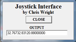
should also work). The joystick interface uses a separate program
(Joystick.exe) supplied with the simulator. Whenever you want to use a
joystick, Joystick.exe must be running. It opens a small window with a CLOSE
button and a text slot that indicates the joystick data. The program uses the
Windows API to get the joystick data and it writes the data as a text string to
a file location. Joystick.exe is located in Simulator\Joystick. The Lua code
running in the player vehicle reads from the file location and converts the
text string to numerical values.
The supported joystick functions are as follows:
X and Y analog values, used for flight control or steering.
The slider analog values, used for throttle control.
Up to sixteen buttons which can be assigned to user-selected
functions.
The POV button is used to pan the view in vehicle internal
and external views.
The wheel is used to select view modes.
Two in-game key commands are used to set up the joystick:
Select flight control mode: CTRL-C
Flight control can be by mouse, keyboard or joystick
(selected mode is indicated by a message).
Calibrate (centre) the joystick: CTRL-J
Ensure the joystick is in its neutral position before
pressing CTRL-J. A message confirms that the joystick has been centred.
The default preset key for joystick control is F9. This should normally
be used in preference to CTRL-C, providing the vehicle has F9 set up for
joystick control (set by the Aircraft Factory settings).
The procedure for using joystick control is as follows:
1. Run the Joystick.exe program (located in Simulator\Joystick). It will open
a small window with a close button and a small window showing the
joystick data.
2. In Sandbox game mode, enter a Constellation and press F9 to activate
joystick control. You will see the flight yokes move in response.
3. Move the joystick slider to the zero position (zero throttle).
4. Press CTRL-J to centre the joystick. You will see the flight yokes move to
the neutral position. When you move the joystick X and Y axes you will see the
flight yokes move in response.
5. Press button 9 to start the engines (or press CTRL-E).
6. Press button 7 for flaps down.
7. Press the POV left-right and up-down positions to pan your view around the
cockpit.
8. Push the joystick wheel down a few times to cycle the views: external,
flypast, tower and back to cockpit.
9. Push the slider forwards to increase throttle. After takeoff you can use the
joystick for flight control. Press CTRL-J to re-centre the joystick as needed.
10. Press button 6 to retract the gear.
The default button assignments are as follows:
1: (the trigger): Fire weapon
2: Brakes
3: Drop bombs
4: Fire missile
5: Select weapon (the weapon that will be fired by the trigger).
6: Gear up/down
7: Flaps up/down
8: Engines on/off
9: Calibrate (centre) the joystick (also CTRL-J)
POV: Pan the view, in cockpit and also for external view.
Wheel: toggle the view mode (cockpit, external, flypast, tower).
Changing the wheel direction reverses the order.
The button assignments are set in Aircraft Factory (AF is included with
the simulator).
To change the assignments:
1. Open AF and select the project for the Constellation (enter
"constellation" into Project Name and click LOAD).
2. Click the Functions1 button:
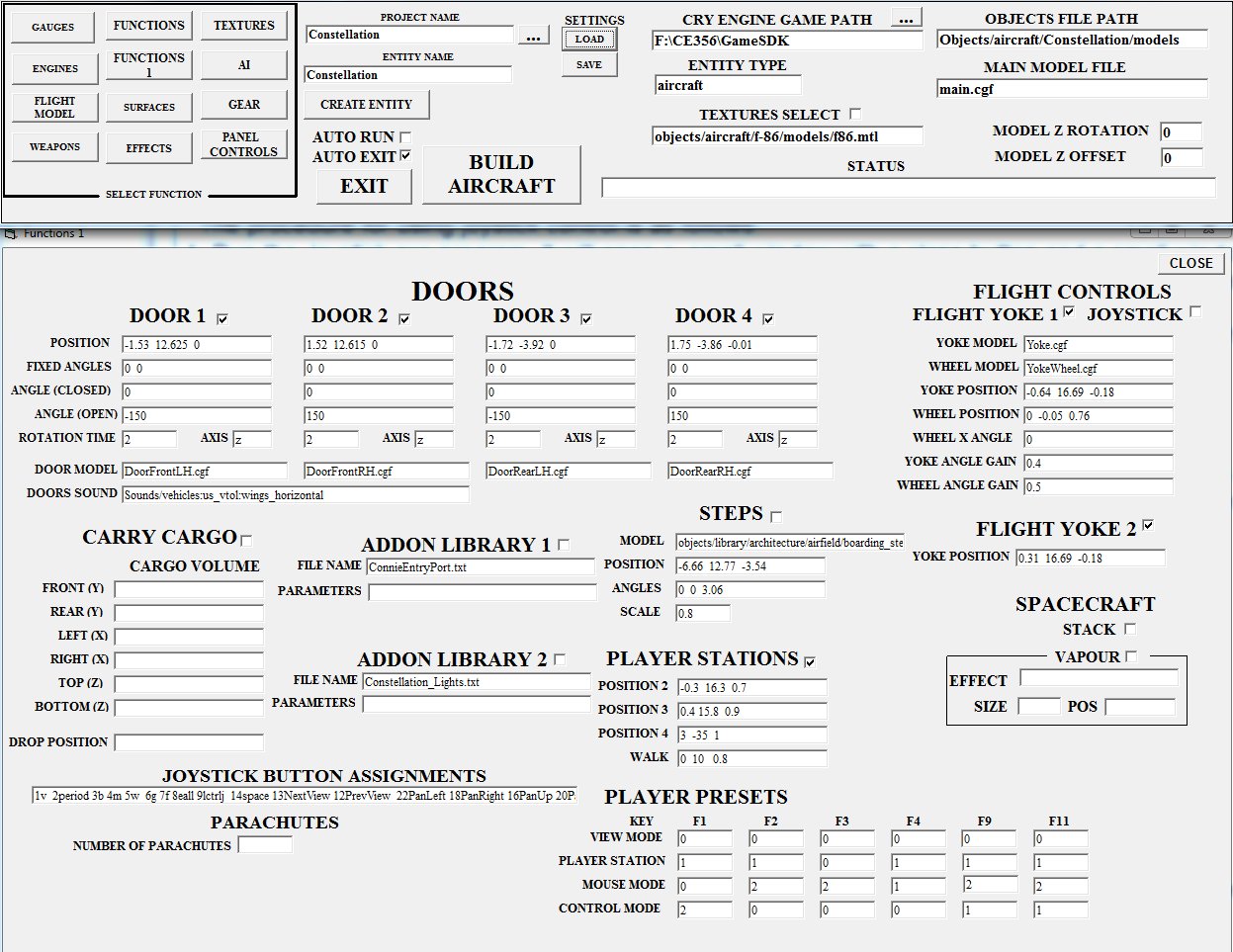
At the bottom left you can see the JOYSTICK BUTTON ASSIGNMENTS slot.
Each entry is a number, which represents the button number, and a command
string. For example, 6g indicates that button 6 controls the gear (G is the
gear up/down command). Seperate each entry with at least one space. By editing
the entries you can easily change the button assignments.
Under PLAYER PRESETS, the entries for F9 show how key F9 selects
joystick control: view mode is zero (internal), player station is 1 (cockpit),
mouse mode is 2 (view panning) and control mode is 1 (joystick). Hover the
mouse over the F1 column to get the required mode values.
PLAYER STATIONS AND WALK MODE
You can jump to one of four preset player stations by
pressing the RIGHT-SHIFT key. Each press toggles the values from zero to 4. Zero
is walk mode and station 1 is the cockpit. Player stations 2 to 4 can have an
aimed gun or can include a rotating gun turret.
To return directly to the cockpit station, press the F1 key. Player
stations or walk mode can also be accessed via the player presets (function
keys F1 to F4, F9 and F10).
Walk mode is selected with F3.
In walk mode you can move in the direction you're facing. Use the two
mouse buttons to walk forwards or backwards (LH button for forwards). You can
look around by moving the mouse. You can walk up and down slopes or climb
stairs, but fortunately you can't walk through walls. If the aircraft has doors
and suitable walking steps are in place, you can even open the doors (key D)
and walk down the steps and then walk on the ground. After stretching your legs
and admiring outside views of the aircraft you could climb the steps, enter
through the door, walk to the cockpit, select normal cockpit mode (key F1),
start the engines and take off. When in flight you could place the aircraft in
auto pilot (command CTRL-A), return to walk mode (F3), walk into the passenger
cabin, take a seat and look through the passenger windows. A later software
version may include a key command to summon a stewardess with a gin and tonic.
Each time you press F3 your view will toggle between the cockpit and your seat
view.
All walk mode commands are accessed from the mouse, as follows:
Walk forwards/backwards: LH and RH mouse buttons.
Adjust walk speed: press the mouse middle button (wheel).
Adjust walk height: roll the mouse wheel (may not be functional in
trains).
You can walk through solid walls by pressing key 1 (one). This can be
useful, for example to enter the interior of the Titanic (there are doors to
the interior but they cannot be opened).
If you need to walk to a location that is blocked by high structures
(e.g. walking back to the locomotive from a wagon) you can achieve this by
rolling the mouse wheel forwards to significantly increase your walk height.
AIRCRAFT SCALING
As you fly away from the Sandbox origin, an annoying problem appears:
the cockpit starts to vibrate and the vibration gets worse as the distance from
the origin increases. This problem occurs because Cry Engine uses low floating
point precision.
The aircraft code has a fix for this annoying problem: scaling. Suppose
by some magic the aircraft is ten times larger. Your view of the cockpit is the
same because, although the cockpit is ten times larger, it is also ten times
further away. Because everything in the cockpit is ten times further away the
vibration appears to be ten times smaller.
You can enable/disable scaling with the command CTRL-S. A message will
confirm that the aircraft has been scaled up or down as appropriate.
The CTRL-S command toggles three scaling modes:
1. No scaling (scale = 1).
2. Low scaling (scale=2). This is primarily intended to ensure nearby objects
in the cockpit are visible e.g. in the Spitfire (the camera NearZ setting doesn't
appear to work in the free SDK).
3. Full scaling. This setting very nearly eliminates the vibration. The scale
increases as the distance from the Sandbox origin increases.
Automatic scaling can be enabled via the aircraft Properties settings.
To change the setting, select the aircraft in Sandbox and open its Properties
rollup. Enter a value of 0, 1 or 2 into the Scaling setting:
No scaling: enter a value of zero
Low scaling: enter a value of 1 (one)
Full scaling: enter a value of 2.
Scaling is enabled only when you are using the cockpit view. For other
external views scaling is disabled, and re-enabled when you return to the
cockpit.
When scaling is active, all slot objects and the player position are
offset by a suitable amount so that the player camera has the same position
with respect to the aircraft pivot (centre), particularly important when
landing and taxiing a large aircraft such as the Constellation. Note:
offsetting must be enabled by the vehicle Properties ScalingOffsets setting.
However, scaling can have an undesirable effect: when taxiing, the
ground may be visible inside the cockpit or passenger cabin. To reduce this
problem, the virtual cockpit can be moved vertically to increase its height
above the ground. This can be adjusted by the aircraft Properties setting
ScalingVertOffset. A typical value for the Constellation is 8. Note: in most
cases this vertical offset is not now required due to the new drawing mode
feature.
In the current simulator version, scaling is not fully compatible with
the carry-cargo feature. When carrying cargo (e.g. the Hercules carrying the
HMMWV) it is recommended that scaling and drawing mode is disabled.
DRAWING MODE
As mentioned in the previous section, scaling virtually eliminates the
cockpit vibration problem. However, as the aircraft may be scaled up by a
factor of ten, there are undesirable side effects e.g. when taxiing, the ground
may appear inside the cockpit or clouds and snow may literally pass through the
cockpit. These problems are solved by a new code feature which controls the
drawing mode.
When drawing mode is enabled, slot objects are drawn in front of all
external objects, even if parts of the external objects are actually closer.
Here's an example. With scaling enabled and in walk mode, you walk to a
passenger window in the Constellation and look out. In the air the view of the
wing and engines looks fine. But when the aircraft has landed and is taxiing,
the view looks weird: much of the wing and engines has sunk into the ground,
due to scaling. But when draw mode is enabled, the wings and engines are drawn
in front of everything else, and the view looks much more normal. Previously
the only fix for this problem was to move the cockpit and passenger cabin
higher up. This stopped the engines from sinking into the ground, but of course
it placed the view unnaturally high. With drawing mode enabled this offset is
unnecessary, and the view looks much more natural.
Drawing mode is automatically asserted when the player is in the
aircraft volume (cockpit or passenger cabin) and automatically disabled in
external view. It can also be permanently disabled/enabled by the aircraft's
Properties EnableDrawMode setting.
The drawing mode can also be controlled in-game with the CTRL-D command.
Each time you press CTRL-D, a message indicates the mode: Draw mode disabled,
draw mode allowed (normal) or draw mode forced on. Draw mode forced on can be
useful when viewing aircraft in front of nearby clouds. This ensures that the
aircraft is drawn in front of the clouds. With draw mode off, aircraft may be
drawn behind the clouds when in fact the clouds are behind the aircraft.
Drawing mode has many benefits: the ground, nearby objects, clouds, snow
and rain do not intrude into the cockpit, and the pilot view has the correct
height. Flying into clouds now looks very realistic.
If drawing mode is enabled, the aircraft Properties scaling settings
should normally be set to:
Scaling
2
ScalingVertOffset
0
Unfortunately drawing mode creates its own problems, for example objects
do not have shadows and internal lights switch off as the player moves away
from them.
PROPERTIES SETTINGS
Many aspects of the aircraft or any Lua vehicle can be set in
their Properties rollup. The Properties of different instances of the same
entity type can be different, and are saved when you save the map. For example,
if you have several F-86's in the map, each one could have a different mix of
weapons.
The main Properties types are:
1. The file names of all models.
2. The AI properties (see 'USING THE AI FUNCTIONS' below for more details).
3. The positions of all animated parts.
4. The weapon properties.
The positions of all animated parts are defined in the Aircraft Factory
settings (and therefore in the Lua file) but you can also adjust them directly
in the Properties settings. For example, to adjust the LH Aileron position, click
the little + symbol to the left of the AileronLHPos item. You can now directly
adjust the X,Y,Z positions. As you make adjustments the LH Aileron will move,
making it easy to get an accurate alignment with the wing.
Note: some non-essential Properties may not be displayed, depending on
the Aircraft Factory settings.
WEAPONS PROPERTIES
Unlimited Weapons: if this is checked, each time you fire an external weapon
(e.g. air-to-air missile) it will be instantly replaced, giving you unlimited
fire power.
External weapons (W1 to W8).
Each weapon is designated as W1 to W8, giving a maximum of eight
external weapons. The settings for each weapon are as follows;
LaunchKey
Enter a single character to define the key command. The standard commands
are 'm' for missile, 'v' for cannon and 'b' for bomb. You can set other
commands, but be aware that most letter keys are already used for other
commands.
Model
The path and name of the visible model that is used until it is launched
e.g. Objects/aircraft/Weapons/Sidewinder/Models/Sidewinder.cgf
Type
The name of the weapon entity class e.g. Sidewinder or Torpedo
Used
Check this if the weapon is actually used. If unchecked the weapon will
not appear and can not be fired.
Pos
Click the little + symbol and then adjust the X,Y,Z position values as
required. The weapon will move as you adjust the values, making it easy to set
up.
IMPORTANT NOTE
When you manually adjust the Properties for a particular aircraft, these
adjustments become permanent when the map is saved, and override the Properties
settings contained in the entity Lua file. Of course, this makes a lot of
sense, but it does create a problem. Here's an example to illustrate the
problem:
1. In Sandbox, I use the Properties rollup to adjust the position of the
ailerons and then save the map.
2. In Aircraft Factory, at a later time I change the aileron positions again. I
rebuild the aircraft and then click Reload Script in Sandbox. But what's this?
Although I changed the Properties settings for the ailerons in the Lua file,
there's no change when I click Reload script.
The explanation is simple: once I made a change manually in the
Properties rollup, it becomes permanent and overrides any settings in the Lua
file.
There is a simple solution: simply delete the aircraft and re-load it,
and load its flowgraph. Note: if this does not work it may be necessary to
reload the map or even to reload Sandbox.
Aircraft Factory has an 'INCLUDE PROPERTIES' check box. If it is not
checked, only Properties settings that customise individual aircraft settings
(e.g. weapons loadout) are retained. For all other settings the values will be
set explicitly by the Lua code via AF settings, and not by Properties. However,
this is currently implemented for very few features.
USING THE AI
FUNCTIONS
To enable all AI vehicles in-game, press the ; key (semicolon).
The simulator AI system provides a number of features:
1. Follow waypoints. You can create a file (usually located at
GameSDK\Data\Waypoints) that contains a list of waypoint positions. Commands
can be executed when a waypoint is reached.
2. Follow a leader. One lead aircraft flies waypoints, while others will follow
it and fly in formation.
3. Attack Nearest Entity. Fighter aircraft will attack specified entities with
cannon, while bombers will use gun turrets to defend themselves. If aircraft
are set both to follow waypoints and attack nearest entity, then fighters will
follow waypoints until they detect approaching enemy entities, at which point
they will break off to attack. Bombers will continue to follow the waypoints
but will use their gun turrets to defend themselves.
4. Auto Start. If this is enabled AI aircraft will start up as soon as the game
starts.
5. Quick Start. If this is enabled AI aircraft will immediately jump into the
air and go to work. If it is disabled then the aircraft will taxi to the runway
and take off or immediately start a takeoff run, depending on specified modes.
AI
PROPERTIES SETTINGS
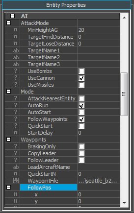
The AI functions for each aircraft are set by its Properties. Select an aircraft,
and in the Properties rollup you will see three items named Mode, AttackMode,
and Waypoints. The options are as follows:
Mode
AttackNearestEntity. If checked, the aircraft will attack the
specified entities which are within range.
AutoRun. If checked, the aircraft flight model will start when
the game starts, otherwise the flight model will run only when it has been
entered by the player or it is in AI mode. If you place some aircraft on a
moving aircraft carrier you should enable AutoRun, otherwise the aircraft won't
follow the movements of the carrier.
AutoStart. If checked, AI aircraft will start as soon as the game
starts. For aircraft which do not have AutoStart enabled, they can be started
in-game by the ; command (semicolon).
FollowWaypoints. If checked, aircraft will fly a path defined by
a series of waypoint positions.
QuickStart. If checked, the aircraft will immediately launch
itself into the air without taxiing. If the aircraft is set up to follow waypoints,
it will fly to the waypoint defined by the Waypoints -> QuickStartN setting,
see below.
StartDelay. In seconds. When AI is enabled the aircraft will wait
the specified number of seconds before starting up. The delay will also apply
if you have enabled QuickStart.
AttackMode
MinHeightAG When an aircraft is attacking a ground target, this
setting determines when it will break off the attack. When the aircraft's
height above ground is less than this value, it will turn away, fly some
distance from the target and then start another attack run, until the target is
destroyed. A typical value is 20 meters.
TargetFindDistance/TargetLoseDistance Sets the distance (in
meters) at which targets can be found and lost.
TargetName (1,2 and 3). TargetName1 defines the primary target
type. When all entities of this type are destroyed or beyond the target find
distance, TargetName2 will be used, and so on.
More specifically, the names are name prefixes. For example, if you
enter TargetName1='Red_aircraft' and TargetName2='Red_tank', then all entities
whose name begins with 'Red_aircraft' will be attacked first. When they are all
destroyed or out of range then all entities whose name begins with 'Red_tank'
will be attacked, and so on. If you used a more general 'Red_vehicle', then all
Red vehicles, and not just tanks, could be attacked. To be even more general,
if you enter 'Red_' then all targets whose names begin with 'Red_' will be
attacked, whether they are aircraft, lorries or ships. By choosing suitable
names for entities in the map, a flexible series of targetting priorities can
be created. By using the prefixes e.g. 'Red_' and 'Blue_' allegiances can be
set.
UseBombs, UseCannon, UseMissiles. These define which weapons are used.
The weapons must be provided by means of the weapons Properties settings. For
air targets you should use cannon and missiles only, but for ground targets you
can use any combination. On each attack pass the aircraft will drop a single
bomb or fire a single missile. The Rocket entity is particularly suitable for
ground attack as it is unguided and will simply fly in the direction it was
launched.
Waypoints
BrakingOnly. When following waypoints on the ground (e.g. taxiing
aircraft), vehicles can avoid collisions by braking or turning away from the
target as appropriate. If BrakingOnly is enabled, vehicles will brake but will
not attempt to turn around the target. Particularly suitable on a cramped
aircraft carrier or for when aircraft are queuing up on the runway. This
setting is also available as a waypoint command, so that it can be
enabled/disabled for specific parts of the waypoint path.
FollowLeader. If checked, the aircraft will follow a lead
aircraft specified by its name.
LeadAircraftName. If this aircraft is to follow a leader, enter
the name of the lead aircraft.
WaypointFile. The path and name of the waypoint file
e.g.data/waypoints/seattle_a_1.txt
Click on the button at the right to browse for the file. Waypoint files
are usually located in GameSDK\Data\Waypoints
QuickStartN. If an aircraft that will follow waypoints has
QuickStart enabled, this setting defines the first waypoint it will fly to. If
the aircraft is following a leader aircraft and the leader lands or is
destroyed, the aircraft will switch to following waypoints. This setting
defines the first waypoint the aircraft will fly to.
FollowPos (x,y,z). This sets the follower aircraft position with
respect to the lead aircraft. If X is set to zero, then this setting is ignored
and the aircraft will take up a random position. X is measured to the right, Y
is measured forwards, Z is measured up (with respect to the centre of the lead
aircraft).
Waypoint
file format.
Waypoint files are usually located in GameSDK\Data\Waypoints. The file
is selected via the aircraft Properties settings.
You can use the simulator editor to create and edit waypoints.
Each waypoint is a point in space that the vehicle will move or fly
towards (the height value is only used by aircraft). If the current waypoint is
12 then the vehicle will move or fly towards waypoint 12.
When it reaches the current waypoint the target waypoint will switch to waypoint
13, and the vehicle will approach that waypoint.
Note: more specifically, the waypoint switches to the next one when the
distance to the current waypoint is less than a specified value. The distance
is typically 20 meters for aircraft, but it may vary for different vehicle
types.
Here is a sample waypoint file:
X Y
Z SPEED
COMMAND P1
P2 P3 P4(TIME) P5 (TEXT)
Waypoint 0, -2365,-745.5, 212,
5, CloseDoor,
0, 0, 0,
0,
,
Waypoint 1, -2365,-745.5, 212,
5,
, 0, 0,
0,
0,
,
Waypoint 2, -2290,-786.5, 212,
5,
, 0, 0,
0,
0,
,
Waypoint 3, -2230,-869.4, 212,
5,
, 8, 10,
0, 0,
,
Waypoint 4, -2216,-980.4, 212,
5, BrakingOnly,
1, 0,
0, 0,
,
Waypoint 5, -2139, -1110, 212,
5,
, 0, 0,
0,
0,
,
Waypoint 6, -2007, -1150, 212,
5,
, 0, 0,
0,
0,
,
Waypoint 7, -1917, -1137, 212,
5,
, 1, 6,
0,
0,
,
Waypoint 8, -1888, -1096, 212,
5,
, 0, 0,
0,
0,
,
Waypoint 9, -1891, -1066, 212,
5,
, 0, 0,
0,
0,
,
Waypoint 10, -1892, -1018, 212,
5,
, 0, 0,
0,
0,
,
Waypoint 11, -1892,-960.6, 212,
5,
, 0, 0,
0,
0,
,
Waypoint 12, -1894,119.45, 250,
80, DoSequence,
1, 4,
0, 0,
,
Waypoint 13, -200, 1500, 300,
80, FollowLeader,
0, 0, 0, 200,
Constellation1,
Waypoint 14, -224, 480,
450,
80,
, 0, 0,
0,
0,
,
Waypoint 15, -230, 435,
600,
80,
, 0, 0,
0,
0,
,
Waypoint 16, -250, 600, 350,
100,DropSpawnedCargo, 10,
0, 0, 30,
HMMWV;Abrams,
COMMAND
P1 P2 P3
P4(TIME) P5 (TEXT)
Sequence 1, GearUp,
150, 0,
0,
5,
,
Sequence 2, NavLightsOff,
0.1, 0,
0,
5,
,
Sequence
3,
FlapsUp, 35,
0, 0,
5,
,
Sequence 4,
SetThrottle, 50,
0, 0,
5,
,
Sequence 5,
SmokeWhite, 0,
0, 0,
5,
,
Sequence
6,
SmokeOff, 0,
0, 0,
0,
,
Sequence
7,
DoLoop, 60,
0, 0,
5,
,
Sequence 8,
GearUp, 0,
0, 0,
0,
,
Sequence 9,
SetThrottle, 50,
0, 0,
0,
,
Sequence
10,
FlapsUp, 0,
0, 0,
0,
,
Each line starts with the 'Waypoint' or 'Sequence' key word and is
followed by a series of parameters. Every number or parameter must be
followed by a comma, even if the parameter is blank.
You can add comments on separate lines, as in the example. No special
comment symbol is required, but comments should not include any commas and they
should not include the "Waypoint" and "Sequence" key words.
The first four parameters after the waypoint number are the X,Y,Z
waypoint position and vehicle speed in meters/second. Note that the speed setting
defines the speed at which the waypoint will be approached.
The parameters fall into two groups. The first group defines the
waypoint position and flying speed. The second group defines an optional task
that will be executed when the waypoint is reached, e.g. to put the gear up,
switch on smoke or play a sound. Each task has four numerical parameters plus
one text parameter. For tasks that require a time duration, the time is always
specified by the fourth numerical parameter.
Sequences of tasks can be added. A sequence is called up at Waypoint 12
in the example (the command is DoSequence). The first two parameters are 1 and
4, meaning that Sequence 1 to 4 will be executed in order. This allows multiple
tasks to be executed at one waypoint. The same sequence group can be called
from any number of different waypoints, rather like subroutines. Exactly the
same tasks can be used on the Waypoint lines and the Sequence lines.
Each Sequence task has four numerical parameters and one string
parameter. The fourth parameter is always the time duration for the task. In
the example, each Sequence task will be executed in turn for 5 seconds, so it
will take 20 seconds to execute all four tasks. As the sequence tasks are
executed the aircraft will fly towards the next waypoint (when a waypoint is
reached the waypoint number is always incremented even if a sequence is to be
executed). You can think of the sequence tasks as a set of subroutines that can
be called up from any part of the main waypoint list.
There are two kinds of tasks: simple and complex. A simple task changes
a variable value e.g. GearUp, FlapsUp, or plays a sound. Complex tasks
completely change the behaviour of the aircraft for a specified time. The
DoRoll task will cause the aircraft to roll at a specified rate for a specified
time (the first parameter defines the roll rate in degrees/second and the
fourth parameter defines how long the aircraft should roll). The AttackGround
task will make the aircraft attack the specified position with cannon (the
parameters are target position (x,y,z) and attack duration).
The waypoint sequence in the example will work as follows:
Waypoint 0: any commands placed in waypoint zero will be executed
immediately the aircraft starts in AI mode. In this example, the doors will be
closed before the aircraft starts to taxi.
Waypoints 1 to 11: taxiing to the runway. The speed is low (5 m/sec,
about 10 MPH).
Waypoint 12: placed beyond the end of the runway, height about 40 meters
above ground. The speed is 80 m/sec (about 160 MPH). After reaching waypoint
11, this will cause the engines to throttle up to maximum and to start the
takeoff run. When takeoff speed is reached, the aircraft will take off and fly
towards waypoint 12.
When waypoint 12 is reached, the DoSequence command will be triggered
(sequence 1 to 4). Sequences 1 to 4 have a time setting of 5 seconds, so each
of the four operations will be executed 5 seconds apart: gear up, navigation
lights off, flaps up and finally set throttle to 50%.
When waypoint 13 is reached the FollowLeader command will be triggered.
The text parameter is 'Constellation1', so now the aircraft will fly toward
Constellation1 and fly in formation. The parameters P1,P2 and P3 set the X,Y,Z
position with respect to the lead aircraft. If P1 is zero, then the values
stored in the aircraft Properties will be used. The parameter P4 is 200, so the
aircraft will follow the lead aircraft for 200 seconds. When the time has
elapsed the aircraft will switch back to following waypoints, starting with
waypoint 14.
LIST OF WAYPOINT COMMANDS
In the following list of waypoint commands and their parameters, P1 to
P5 are the five parameters. The time parameter is always placed in P4 and text
parameters are always placed in P5.
TASK
NAME
DESCRIPTION
P1
P2
P3 P4 (time)
P5 (text)
GearUp
Put the undercarriage (gear) up
GearDown Put the
undercarriage down
FlapsUp
Put the flaps up
FlapsDown Put the flaps
down
SmokeRed Red
smoke on
SmokeWhite White smoke on
SmokeBlue Blue
smoke on
SmokeOff
Smoke off
NavLightsOn Navigation lights
on
NavLightsOff Navigation
lights off
PrintMessage Print a text message for a
specified time.
P1: X screen position (percent) P2:
Y screen position (percent) P3: Message duration time in
seconds P5: Message text
Screen X Y position is given in percentage values (50, 50 is the
centre of the screen, Y is zero at top of screen)
PlaySound
Play a sound
P1: Volume (maximum volume if P1=1). P5: Sound
file path.
DoRoll
Aircraft rolls for a specified time
P1: Roll rate
(degrees/second) P4: Time
DoLoop
Aircraft loops for a specified time
P1: Loop rate (degrees/second)
P4: Time
FlyStraight
Aircraft flies straight for a specified time (current pitch and bank angles
retained)
P4: Time
FlyLevel
Aircraft flies level for a specified time (zero bank and pitch angles)
P4: Time
AttackGround Aircraft attacks ground target
with cannon.
P1: Target X position P2: Target Y
position P3: Target Z position P4:Time duration of the attack.
FollowLeader Vehicle will follow
lead vehicle for a specified time.
P1: X P2: Y P3: Z
P4:Time P5: Lead aircraft name e.g. "Constellation2"
The XYZ values are local coordinates with respect to the lead aircraft
e.g. if x is increased the aircraft will move further to the right of the lead
vehicle.
KBDCommand Execute a keyboard command e.g. 'h' to
sound the horn.
P5: Keyboard string code .e.g. "h"
(without the quotation marks).
SetDoors Close
or open selected doors (door 1 to 4). The parameters P1 to P4 set the door
status: 0 (zero) = closed, 1 (one) = open.
P1: Door 1 status P2: Door 2
status P3: Door 3 status P4: door 4 status.
DropBombs Drop bombs
for the specified time period.
P4: Time
DropChutes Spawn and
drop paratroops for a specified time period.
P4: Time
DropCargo Drop
the cargo entities (e.g. vehicles or AI soldiers)
P4: Time allocated for the drop, in seconds.
DropSpawnedCargo Spawn and drop the specified entities.
P1: Time allocated for the drop, in
seconds P5: list of entity types, separated by semicolons
e.g. Hummer;TankA;LorryA;WalkerA
BrakingOnly Sets whether AI vehicle will
use steering to avoid collisions on the ground (e.g. taxiing aircraft).
P1: Sets braking variable
If P1=0 then steering and braking will be used. If P1=1 then only braking
will be used (e.g. when on the runway or on the aircraft carrier where space is
limited).
SetAnimation
Sets a new animation for a character (the Walker entity).
P1: Animation loop time. If the
animation does not include character translation (forward movement) then set to
zero.
P2: Animation
loop distance (the forward distance moved by the character in each loop, set by
the animation).
P3: Disable height checks. If height
checks are disabled, character will move at constant height, useful for
animations which execute above an object e.g. standing up from a chair. 1 =
disable checks. 0 = enable checks.
P5: Animation name.
Many animations move the character forward e.g. a walking animation.
When the loop resets to zero the character will move back. The code compensates
for this by moving the entity the same distance forwards. The P1 animation loop
time sets when the entity will be moved back. It should be slightly less than
the actual loop time to ensure the condition is executed. The P2 animation loop
distance sets the forward distance (the distance the entity will be moved when
the animation loops back to zero).
If the character animation does not include forward translation (e.g. the
pigeon or rooster) then P1 should be set to zero. This will disable the forward
movement when the animation loop resets to zero. P2 sets the forward
translation speed (the movement in meters per frame).
Some example animations:
P1 P2
P3
P4
P5
0.94 1.05
0
0 relaxed_tac_walk_rifle_fwd_slow_3p_01
0.96 2.6
0 0
relaxed_tac_run_nw_fwd_fast_3p_01
Standing up, height checks disabled, 2.8 seconds before next
animation set.
0
0 1
2.8 relaxed_tac_sitexit_nw_3p_01
Rooster, animation does not include forward translation, P2 sets forward
movement per frame.
0
0.01 0 0
walk_loop
SetCombat
Sets the combat mode for a vehicle with gun positions following waypoints e.g.
the tank or B-25. It enables/disables a specified gun position and also sets
the target name.
P1: Enables/disables combat
mode. 0 = combat disabled (gun will not fire). 1 = combat enabled.
P2: Specifies the gun position
number (values 1, 2, 3 or 4).
P5: Sets the target name
e.g. Waypoint 2, -35217.8, -15853.4,
172.546,
15,
SetCombat,
1,
1,
0,
5,
Tank4,
This enables combat for gun position 1 and sets Tank4 as the
target name. Any vehicle whose name begins with Tank4 will be targetted (e.g.
Tank4A).
SetWpt
(or GoTo)
Sets the target waypoint number to a new value. This can be used to make a
waypoint sequence repeat indefinitely. Optionally the waypoint number can be
chosen randomly from four possible values.
P1: The waypoint number.
P2, P3, P4: optional waypoint numbers used if random mode is selected.
P5: Sets random mode. If P5 contains the key word "Random" then
random mode is selected (waypoint number is chosen randomly from the values in
P1 to P4). Otherwise the waypoint number is set by P1.
Waypoint 10, 8161.03,
-639.884, 500,
150, SetWpt,
12, 18,
26, 31, Random,
Waypoint 20, -618.668, -377.099,
14.7, 20,
GoTo,
1, 0,
0,
0,
,
In the first example above, random mode is selected. The waypoint number
will be randomly selected from the values 12, 18, 26 and 31.
In the second example the waypoint number will be set to 1 and the
vehicle will move towards waypoint 1.
SetBranching
(or SetPoints)
Sets the branching override variable (allows an AI train to switch to a branch
line or stay on the main line, irrespective of the Points setting).
P1: The override value 0 = neutral (branching set by
Points) 1 = Force train to stay on main line 2 = Force
train to switch to the branch line.
When this command is executed, all carriages in the train will be set to
the specified value, thus ensuring that the entire train follows the same
track.
StopTrain
The train vehicle (usually the locomotive) will stop at a specified position.
P1: Sets the stopping distance in meters.
P2: Restart mode. If set to zero, the train will start up again
after the time set by P4 has elapsed. If set to 1 (one), the handbrakes are
applied and the train will remain stationary until a Resume command is executed.
P3: Sets relative or
absolute stopping mode. If zero (relative) the train will stop over the
distance set by P1. If non-zero, the value sets the absolute stopping position
(distance along the track in meters).
P4: sets the duration of
the stop, in seconds (applies only if P2 is
zero).
After the time has elapsed the locomotive will start up and
proceed towards the next waypoint.
If stopping uses an absolute position (P3=1) P1 should be set to a
value approximately equal to the stopping distance (distance between the
waypoint and the stopping position).
StopShip
The ship will stop at a specified position and heading. It can be restarted
after a set time period (relative) or by the Resume command (absolute clock
time).
P1: Heading
(degrees, zero heading = north, increases clockwise).
P2: Target X
position.
P3: Target Y
position.
P4: Time
delay before restarting ship (seconds).
P5: Sets
relative or absolute start time. For relative time (set by P4), leave P5
blank. For absolute clock time, enter the keyword "Stop"
If P5 has the "Stop" keyword, then the ship will stop (paused)
until started up again by a following Resume command.
StopCar
The ground vehicle will stop at a specified position and heading. It can be
restarted after a set time period (relative) or by the Resume command (absolute
clock time).
P1: Heading
(degrees, zero heading = north, increases clockwise).
P2: Target X
position (unless overridden by SetParkingPos command).
P3: Target Y
position (unless overridden by SetParkingPos command).
P4: Time
delay before restarting vehicle (seconds).
P5: Sets
relative or absolute clock time.
For relative
time, leave P5 blank. For absolute clock time, enter the keyword
"Stop" e.g.
Sequence 1,
StopCar,
0, 10,
50, 260,
Stop,
If P5 has the "Stop" keyword the vehicle will stop (paused)
until started up again by a following Resume command.
The parameters for StopShip and StopCar are identical, but the
appropriate command depending on the vehicle type must be used.
If the SetParkingPos command has
been previously executed, the X,Y positions will be set by SetParkingPos, and
not by P2 and P3.
If the car is to stop on a parent vehicle (a ship,
train wagon or cargo aircraft) then the X,Y position and heading values must be
in local coordinates with respect to the parent vehicle.
e.g. P1=0 P2=0 P3 = 50 (Heading = 0,
X = 0, Y = 50) The car will stop on the ship's centre line and near the
bows, and pointing towards the bows. If the heading is set to 90 then the car
would be pointing to the right side of the ship. For best results, ensure the
waypoints leading up to the StopCar command give the vehicle a heading close to
the target heading.
BrakesOn Apply brakes
and set zero throttle to stop the vehicle for a time period. Optionally the
vehicle can be stopped until re-started by a Resume command.
P4: Time period in seconds.
P5: Stopping mode. If
the keyword "Stop" is placed in P5, then the vehicle will remain
stopped until re-started by a Resume command.
e.g. Sequence
11, BrakesOn,
0,
0,
0,
10,
Stop,
BrakesOn will execute for 10
seconds, but vehicle will remain stopped until re-started by a Resume command.
For ships only: P1 sets the braking strength, typical value 0.2 to 1.0,
larger values will stop the ship quicker.
SetParkingPos
This sets the X,Y position where a ground vehicle will stop (e.g. on a
ship). The X, Y position can be absolute (world) or relative to the parent
vehicle e.g. the ship. It also sets a time delay for each vehicle. When the car
is restarted by the Resume command using clock time, the car will wait for the
additional time delay. This can be used to ensure that a group of cars do not
start at the same time. The position will be used by the next StopCar command.
This command can set different positions and time delays for a number of cars
e.g.
Waypoint 1, -3563, -160,
0, SetParkingPos, 0, 0, 0,
0, AstonMartin2 -10 50 0 Beetle1 -7 50 10 Lorry1 -1 50 20,
In this example, when the Resume command is executed using clock time,
the cars will start at ten second intervals (time values 0, 10, 20).
The Beetle will park itself at x = -7, y = 50, and its extra start delay
will be ten seconds.
P5: A list of
vehicle names and their X,Y positions and time delays. Separate each name and
X,Y, time value by at least one space.
Resume
(or Start)
If the vehicle has been permanently stopped by a previous stop
command (StopTrain, StopShip, StopCar or BrakesOn with the Stop option), Resume
must be used to restart the vehicle. The Resume trigger is based on relative or
clock time and also an optional external trigger condition.
P1: Clock time (hours)
P2: Clock time (minutes)
P3: Clock time (seconds)
P4: Time delay before
restarting (seconds).
P5: Optional trigger condition
The start time can be relative or absolute (clock time), depending on
which occurs first. Timeout will occur when either of these conditions occur:
1. The waypoint timer exceeds the P4 value in seconds (relative time).
2. The clock time exceeds the time set by P1, P2, P3 plus the time offset
(clock time).
For example, to ensure absolute clock time is used, set P4 to a large
value such as 9999. To ensure relative time is used, set P1 (hours) to 9999.
This command can be called by the Resume or Start
names. The command can be placed in waypoint zero (or in a sequence called from
waypoint zero). This will cause the vehicle to start initially at a specified
clock time without the need to reach a waypoint. In this case the name Start is
more appropriate.
Resume: Conditional
Triggering
The timeout (relative or clock time) can be combined with a specified
condition in a target vehicle. For example, parked cars executing Resume can be
programmed to wait until a ferry's cargo doors have opened, or until the target
vehicle has reached a specific waypoint. The parameters for conditional triggering
are placed in P5 e.g.
Sequence
3,
Resume, 9999,
5, 0, 9999,
ShiraB2 Or Door1Open 0 0,
P5 contains five parameters separated by one or more spaces e.g.
ShiraB2 Or Door1Open 0 0
The trigger conditional is optional. If no trigger condition is used
leave P5 blank (spaces only).
The five parameters placed in P5 are as follows:
Parameter 1: a text string e.g. a vehicle name or a file path
Parameter 2: defines whether the trigger condition should be AND'ed or
OR'ed with the timeout condition. Values are "And" or "Or".
Parameter 3: sets the name of the trigger type e.g.
"Door1Open".
Parameters 4 and 5: two numerical values.
Trigger Types
Door1Open, Door2Open, Door3Open or Door4Open: resume will be
triggered if the specified door in the target vehicle is open.
Parameter 1: sets the target
vehicle name.
Parameter 2: sets whether the trigger is AND'ed or OR'ed with the
timeout condition.
Parameter 3: the trigger name.
Parameters 4 and 5: not used, set to zero.
WpntN: resume will be triggered if the waypoint number in the
target vehicle is equal to or greater than the value specified by the fourth
parameter.
Parameter 1: sets the target vehicle name.
Parameter 2: sets whether the trigger is AND'ed
or OR'ed with the timeout condition.
Parameter 3: the trigger name.
Parameter 4: sets the waypoint number.
Parameter 5: not used, set to zero.
e.g. Sequence
3,
Resume, 9999,
9,
0, 70,
AstonMartin_10 And WpntN 5 0,
In this example resume will be triggered when it has been running
for more than 70 seconds AND AstonMartin_10 has a waypoint value of 5 or greater
i.e. the AstonMartin has reached waypoint 4.
WpntDisable: resume will be disabled if any vehicle running a
specified waypoint file has a waypoint value in the specified range.
Parameter 1: path of the waypoint file: any vehicle running
the file can disable resume.
Parameter 2: sets whether the trigger is AND'ed or OR'ed with the
timeout condition.
Parameter 3: the trigger name.
Parameters 4 and 5: sets the waypoint range (lower value first).
e.g. Sequence
12,
Resume, 9999,
0,
0, 20,
data/waypoints/HarbourDemoA/Phantom_AI_landing_taxiing.txt And
WpntDisable 10 13,
In this example, resume will be disabled if any
vehicle is running the specified waypoint file and its waypoint number is in
the range 10 to 13. Any vehicle meeting both conditions will be in a set range
of positions, for example aircraft making their final approach to the carrier.
This will cause aircraft running Resume to wait for all aircraft on final
approach to land, before taxiing out for takeoff. It effectively stops
collisions between taxiing and landing aircraft.
AddTimeOffset
Adds a specified value to the time offset variable. This allows vehicles to
resume at a clock time later than that specified in the Resume command.
P1: Time to be added to the time offset (minutes).
If a waypoint sequence is repeated (e.g. by the SetWpt or GoTo command),
each time AddTimeOffset is executed the time offset is increased. For example,
if P1 = 30, then the waypoint sequence will be repeated every 30 minutes. A
value of 1440 would add a one day delay.
SetParentVehicle This sets a named vehicle as the target
parent e.g. the aircraft carrier. It can set different target parents for any
number of vehicles. It also sets local coordinates, so the vehicles following
waypoints will use local coordinates with respect to their parent. While
SetParentVehicle is in effect, all following waypoints in the list should be in
local coordinates. This command can set different parent vehicles for a
number of cars e.g.
Sequence 2, SetParentVehicle, 0, 0,
0, 0, AstonMartin4 LocomotiveA12 Beetle3 LocomotiveA6 LorryA2
LocomotiveA7
P5: A list of
vehicle names and their parent names. Separate each name by at least one space.
This command is particularly useful where a group of cars are to drive
onto train wagons. After the command is executed, each car will drive to its
assigned wagon.
SetLocalCoords This sets world or local coordinates. If
world coordinates are set, then X,Y,Z waypoint values are standard Sandbox
world coordinates. If local coordinates are set, then X,Y,Z waypoint values are
local coordinates with respect to the specified parent vehicle e.g. an aircraft
carrier.
P1: Sets world or local
coordinates. 0 (zero) = world coordinates. 1 = local coordinates.
P5: Name of parent
vehicle
Waypoint 1, -38000,
-15000, 1800,
50, SetLocalCoords,
1,
0,
0, 5, AircraftCarrier1,
Waypoint 2,
1, -3000,
500,
80,
,
0,
0,
0,
0,
,
In this example, waypoint 1 sets local coordinates with
respect to AircraftCarrier1. Waypoint 2 sets X,Y,Z in local coordinates, so the
aircraft will fly towards a point 3 km behind the aircraft carrier and 500
meters above it in readiness for landing.
SetParentMode
Normally a vehicle attached to a parent (e.g. a car on the aircraft
carrier) will lose attachment if it momentarily loses contact with the
parent.This command allows the car to be permanently attached even if it drives
off the carrier. If a landing aircraft collides with a car the car may lose
attachment and fall off the carrier.This will not happen if this command is
asserted.
P1: Sets attachment mode 0
(zero) = normal mode, vehicle will lose attachment if it loses contact with the
parent.
1 (one) = override mode, vehicle will be
permanently attached to the parent (until another SetParentMode command is
executed).
This command is particularly useful if a number of AI vehicles are
operating in a confined space e.g. on an aircraft carrier.
SetValue
Sets a Lua variable or variables to a specified value. P1 and P2 contain
the values to be used. The keyword placed in P5 defines the Lua variables that
will be updated, as follows:
1. EngineTilt: the engine tilt angle will be set by P1.
e.g.
SetVariable, 30, 0, 0,
0, EngineTilt, Sets the Harrier
engine tilt to 30 degrees
2. SwingWing: the aircraft wing angle will be set by P1.
e.g. Sequence
8,
SetValue,
2,
0, 0,
0,
SwingWing, Sets the F-14 wings
to swept back (high speed).
Values for SwingWing are 1 = swept forward (low speed) 2 =
swept back (high speed or taxiing on the carrier)
3. StayAttached: the StayAttached Lua variable is set by P1.
If P1 = 1 then StayAttached is true: e.g. an aircraft will remain
attached to the carrier even if a disturbance (e.g. a collision) would
otherwise cause the aircraft to be detached.
4. BrakingOnly: the BrakingOnly Lua variable is set by P1.
If P1 = 1 then BrakingOnly is true: when AI aircraft detect a
collision, they will stop and apply brakes, and not attempt to steer around the
obstruction.
5. Filtering: height and pitch smoothing will be applied to AI aircraft,
usually during takeoff and landing.
e.g. Sequence 11,
SetValue, 0.03,
0.01,
0,
0, Filtering,
Height smoothing = 0.03, pitch smoothing = 0.01
The smoothing values are set by P1 and P2:
P1: Height smoothing. The smaller the value, the
greater the smoothing (the value sets the maximum height change per frame).
P2: Pitch smoothing. The smaller the value, the
greater the smoothing (the value sets the maximum pitch change per frame).
If P1 = 0 then no smoothing will be applied.
6. SimpleMode: enables the AI simple mode to be overridden. When simple
mode is active, the vehicle runs a highly simplified follow waypoints system in
order to increase frame rates.
P1: The simple mode override value.
0 = no override. 1 = Force simple mode on.
-1 = Force simple mode off.
VEHICLE ATTACHMENT
Simulator vehicles can be attached to other vehicles. For example, if an
aircraft lands on the aircraft carrier, the aircraft is automatically made a
child of the aircraft carrier. It will be "carried" by the aircraft
carrier. While attached, the aircraft will use local coordinates with respect
to the carrier. This allows the aircraft to taxi on the carrier and make its
takeoff run.
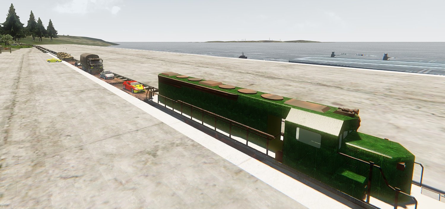
In the example shown above, the cars, lorries and tanks running in AI
mode have parked themselves on the train wagons. Each vehicle has automatically
been attached to its parent wagon (the wagon is the parent, the vehicle is the
child). When the train moves out the vehicles are carried as cargo.
The Harbour Demo map demonstrates vehicle attachment:
1. An AI lorry drives into the Hercules cargo hold. The Hercules takes off,
carrying the lorry as cargo.
2. AI cars and lorries drive onto the aircraft carrier deck. When the carrier
moves off it carries the vehicles on its deck.
3. AI vehicles drive onto the train wagons. When the train moves off it carries
the vehicles on the wagons. When the train stops at the station the vehicles
move off the train and drive away, following waypoints.
A Properties setting (Parent) enables a vehicle to be a parent. In the
examples above, the Hercules, aircraft carrier and train wagons have
Properties/Parent checked (enabled). When a car drives onto the aircraft
carrier, it will detect the carrier and check the carrier's Properties/Parent
setting. If enabled, it will automatically attach itself to the carrier. If
following waypoints, the car switches to local coordinates centred on the
carrier. This allows vehicles (including the Walker entity) to follow waypoints
on the deck even when the carrier is under way.
You can manually drive vehicles into the Hercules cargo hold. As each
vehicle enters the hold it automatically attaches itself to the Hercules (of
course, the Hercules Properties/Parent setting must be enabled). You can then
take the Hercules for a flight and, after landing, drive the vehicles out
again. To try this, load the map Tutorial_cargo and follow the instructions.
SAVING
AND LOADING GAMES
At any time in-game you can save the current state of all simulator
vehicles (aircraft, trains, ships etc). For example, if you are in a Spitfire
about to attack a group of Heinkels you can save the game, allowing you to
re-run this situation any number of times. You can also set up the map so that
when you press CTRL-G for game mode a situation is immediately loaded and run
(instant action). For example, as soon as you start game mode you are instantly
in the Spitfire about to attack the Heinkels.
Saved games can also be selected and loaded from a menu.
Saved game files are normally saved to GameSDK/Data/SavedGames.
Saving and loading games is implemented by the
AircraftControl entity, so one instance of this entity must be loaded into the
map.
AircraftControl has several Properties settings (under Scenarios) that
control saved games.
The NamePrefix Properties setting defines the name prefix of saved game
files. This allows each map to have its own set of saved game files.
For example, if the map name is ConstellationFlight then NamePrefix
could be set to 'ConstellationFlight_'. The file name of the first saved game
will then be ConstellationFlight_SavedGame1.txt and so on.
To save a game:
1. Press the number pad minus key (normally at upper right hand of
keyboard). You will see a prompt to enter a number or letter.
2. To save the game, press one of the number keys 0 to 9 or any letter
key such as 'a' or 'b'. Ensure that number or letter has not already been used,
as it will overwrite the existing saved game. A screen message will confirm
that the game has been saved.
Quick Save/ Load.
Press key Q to quick save the game. To recall it, press key R.
LOADING GAMES
To load a game, press the BACKSPACE key. If a saved game menu has been
set up, the menu will appear.
You can immediately press a number or letter key to load a game.
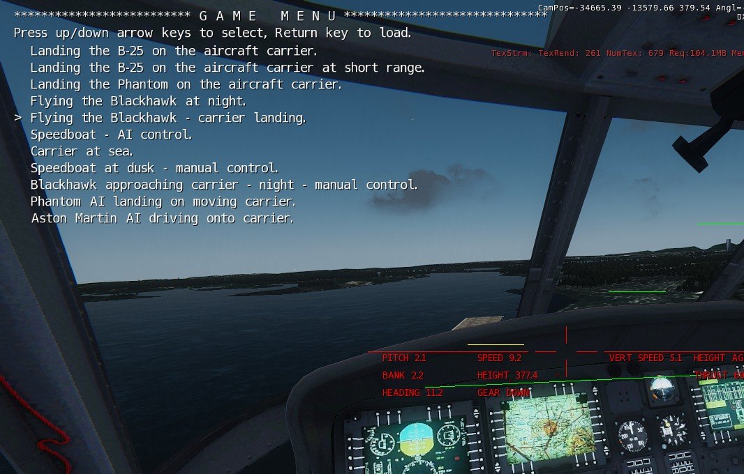
To use the saved game menu, press the up and down arrow keys to select,
or roll the mouse wheel. You can also move up or down ten lines at a time by
pressing the left and right arrow keys. The > character is placed to the
left of the selected game. To load the game, press the RETURN key or press any
mouse button.
To set up a new saved game menu:
1. Create a game list text file e.g.
GameSDK/Data/SavedGames/VehicleLoadingTest_SavedGame1.txt,
Landing the B-25 on the aircraft carrier.,
GameSDK/Data/SavedGames/VehicleLoadingTest_SavedGame2.txt, Landing the
B-25 on the aircraft carrier at short range.,
GameSDK/Data/SavedGames/VehicleLoadingTest_SavedGame3.txt, Landing the
Phantom on the aircraft carrier.,
GameSDK/Data/SavedGames/VehicleLoadingTest_SavedGame4.txt, Flying the
Blackhawk at night.,
GameSDK/Data/SavedGames/VehicleLoadingTest_SavedGame5.txt, Flying the
Blackhawk - carrier landing.,
GameSDK/Data/SavedGames/VehicleLoadingTest_SavedGame6.txt, Speedboat - AI
control.,
GameSDK/Data/SavedGames/VehicleLoadingTest_SavedGame7.txt, Carrier at
sea.,
GameSDK/Data/SavedGames/VehicleLoadingTest_SavedGame8.txt, Speedboat at
dusk - manual control.,
GameSDK/Data/SavedGames/VehicleLoadingTest_SavedGame9.txt, Blackhawk
approaching carrier - night - manual control.,
GameSDK/Data/SavedGames/VehicleLoadingTest_SavedGamez.txt, Phantom AI
landing on moving carrier.,
GameSDK/Data/SavedGames/VehicleLoadingTest_SavedGameA1.txt, Aston Martin
AI driving onto carrier.,
Each line contains the path to the saved game file, and the description
text that will appear. Both the path and description must be followed by one
comma. Ensure there are no commas in the path or description.
2. Save the file with a suitable name into GameSDK/Data/SavedGames.
3. Select the AircraftControl entity and enter the path to the file from Step 1
in Properties - GameListFile.
4. Save the map to make this setting permanent.
SAVED GAME FILE FORMAT
Here is part of a saved game file:
PILOTED AIRCRAFT 5,
PLAYER POS -10538.7, 9068.89, 358.44, 63.35,
PLAYER STATION 1,
MOUSE MODE 0,
JOYSTICK MODE 2,
TOD 15.5,
SKYDOME objects/clouds/skydomes/sky_dome_e.mtl,
AIRCRAFTN 1,
NAME Constellation4,
AIRCRAFT POS -28878.5, -18855.8, 225.843,
AIRCRAFT VELOCITY 0, 0, 0,
AIRCRAFT ANGLES 0, 0, -21.13,
ANGLES V 0, 0, 0,
AIRCRAFT RUNNING 0,
AI_VALUES 0, 0, 0, 1, 0,
NUMBER OF ENGINES 4,
THRUST 0,
GEAR UP 0,
FLAPS DOWN 0,
AIRCRAFT LIGHTS ON 0,
AIRCRAFTN 2,
NAME Phantom2,
AIRCRAFT POS -28464.3, -19884.8, 224.558,
AIRCRAFT VELOCITY 0, 0, 0,
AIRCRAFT ANGLES 0, 0, 0,
ANGLES V 0, 0, 0,
AIRCRAFT RUNNING 0,
AI_VALUES 0, 0, 0, 1, 0,
NUMBER OF ENGINES 2,
THRUST 0,
GEAR UP 0,
FLAPS DOWN 0,
AIRCRAFT LIGHTS ON 0,
AIRCRAFTN 3,
NAME Constellation1,
AIRCRAFT POS -18789.8, 8723.83, 235.577,
AIRCRAFT VELOCITY 0, 0, 0,
AIRCRAFT ANGLES 0, 0, -179.61,
ANGLES V 0, 0, 0, etc.........................
������������������ �����������������������EDITING SAVED GAME
FILES
You can easily edit an existing file to change the setup. By changing the
PILOTED AIRCRAFT setting you can place the player in a different aircraft. The
X Y Z settings define the aircraft position, and VX VY VZ define the speeds
etc.
The saved game files set which vehicle you will be flying or driving.
You can select a different aircraft as follows:
1. Select AircraftControl1 and open its Properties rollup.
2. In the Properties setting Scenarios - PlayerVehicleName, enter the name of a
vehicle.
You will then start the game in the named vehicle. If you enter a
non-existent name e.g. xxx, you will stay in normal player mode.
To return to normal mode (aircraft selected by the saved game file),
delete the aircraft name so that the entry is blank.
3. You can also change the vehicle type. In PlayerVehicleType, enter a vehicle
class name e.g. "Constellation" or "B737".
������������������������������������������ LIST
OF SAVED GAME GLOBAL COMMAND
� Saved game files start with a block of global
commands, followed by a block of commands for each vehicle. The global commands
are as follows:
PILOTED
AIRCRAFT� n,���� This defines which is the piloted / player
vehicle. Each vehicle block starts with e.g. AIRCRAFTN 19 The value of n
defines which is the piloted / player vehicle.
PLAYER
POS x, y, z,� This defines the local
position of the player (the active camera) inside the vehicle. X is to the
right, y is the forward position, z is the height.
PLAYER
STATION n, This defines the player station in the vehicle. 0 = walk mode and 1
= the cockpit position. 2 to 4 define 3 additional positions (set by Aircraft
Factory).
�MOUSE MODE n,
JOYSTICK
MODE n,
TOD
n, This sets the time of day. A value of 12.5 would set a time of 12:30.
CLOUDS
n clouds, size min, max, height min, max.����
This sets the clouds (it sets Property values in the TerrainControl
entity). n clouds sets the number of clouds for each terrain grid. The other
values set the cloud min and max size and height (the code chooses random
values inside these min and max values.
RAILTRACKS
ROADS rail_tracks, roads,��� This setting
enables or disables autogen rail tracks and roads. 0 = disable and 1 = enable.
SKYDOME
n,���� This setting defines the sky dome
that will be loaded.
CLOCK
TIME days, hours, minutes, seconds,��������
This sets the world clock time.
AUTOGEN
enabled, density,��� This
enables/disables and sets the density of the area autogen (not for the world
system). The density range is 0 to 1 (1 sets full object density).
�
������������������������������������������
LIST OF SAVED GAME VEHICLE COMMANDS
INSTANT ACTION MAPS
You can set up AircraftControl so that a saved game will be loaded when
you press CTRL-G for game mode.
Procedure:
1. Select AircraftControl and open its Properties rollup.
2. Check AutoPlay to enable instant action.
3. Click on AutoPlayLoadFile, browse to Data\SavedGames and select a saved game
file.
If the AutoPlayRandom tick box is enabled, the saved game will be
randomly selected, so each time you start game mode you'll get a different
game.
If you enter a valid vehicle entity name (e.g. Constellation2) into the
PlayerVehicleName setting, you will start the game in that vehicle (normally
the vehicle is defined by the save game file).
AIRCRAFT CONTROL SAVED GAME (SCENARIO) PROPERTIES
SETTINGS
The following Properties are located in the Scenarios section.
AutoPlay: if enabled, the selected saved game will be loaded
automatically when the game starts (CTRL-G).
AutoPlayLoadFile: the path to the saved game file that will be
loaded if AutoPlay is enabled.
AutoPlayRandom: if enabled, the saved game will be chosen
randomly.
ForceVehicleLightsOn: if enabled, all vehicles defined by the
saved game file will have their lights on.
NamePrefix: the name prefix appended to saved game files when
they are saved.
PlayerVehicleName: normally, when a saved game file is loaded the
player vehicle is specified by the name in the file. But if this setting is
non-blank, the player will be placed in a vehicle defined by this name.
PlayerVehicleType: this overrides the saved game file by setting
the player vehicle entity class e.g. "Constellation" or
"AstonMartin".
AircraftControl
Entity
The AircraftControl entity controls many global aspects of the
simulator, and provides functions such as in-game tutorials and in-game help.
The simulator can be customised in many ways by changing its Properties
settings.
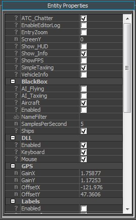
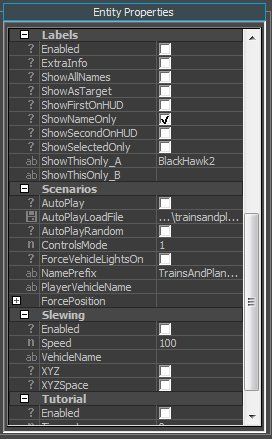
AircraftControl
Properties
The Properties settings are as follows:
AIAutoStart: if enabled, all AI vehicles in the map will automatically
start (AI vehicles can also be started manually with the ; (semicolon) command,
or they can be set to auto start from their own Properties setting).
ATC_Chatter: enables random ATC voices in aircraft which have this
feature (set in Aircraft Factory).
ControlsMode: a drop-down menu that selects the default control mode for
all simulator vehicles in the map. Options are Combat and Normal.
EnableEditorLog. Disabled by default. If disabled, the game will not
write to the editor log. If enabled, writing to the editor log may cause
regular pausing.
EntryZoom: enables a zoom effect when entering a simulator vehicle.
GameListFile: sets the path to the text file that contains the menu of
available saved games.
HUD: a drop-down menu that selects the default HUD mode for all aircraft
in the map. Options are Civil, Military and None.
ScreenY. The custom DLL automatically senses the screen height (Y). If a
non-zero value is entered, the value is used instead, usually if the custom DLL
is not used. The simulator uses the screen height to automatically scale and
position text. If the custom DLL is used (strongly recommended), ensure this
value is set to zero.
Show_Info. Enables display of the standard Sandbox info at top of
screen, including the FPS display. The info display is automatically disabled
if an in-game tutorial is enabled (tutorial and info text may overwrite each
other).
ShowFPS. Enables display of a filtered FPS value (a rolling average of
the last 1000 frames). It also displays the filtered frame rate after 100
seconds.
VehicleInfo. If enabled, displays extra information for the nearest
simulator vehicle (can also be activated in-game by the I (Information)
command).
VehicleInfoName. If a vehicle name is entered, information will be shown
for this vehicle. If left blank, information will be shown for the nearest
vehicle.
BlackBox. Used for code debugging.
Clock Settings for the real world clock.
ClockSpeed. Sets the clock speed. A value of one
gives normal clock speed, while a value of 2 would make the clock run twice as
fast.
Enabled. Enables/disables the clock.
StartTime (Hours and minutes). Sets the real
world time when the game starts.
DLL
Enabled. Enables overall custom DLL functions.
Keyboard. Enables custom DLL keyboard function.
Mouse. Enables custom DLL mouse functions.
When the custom DLL is used (for 3.56 and 3.58) then
all three check boxes should be ticked (enabled).
GPS. Provides gain and offset calibration values for the
latitude/longitude readout (for real world terrain).
Labels.
Enabled. Enables the display of labels on simulator vehicles
(can also be activated in-game by the I (Information) command).
ExtraInfo. Enables display of extra information e.g.
waypoint distance and bearing.
ShowAllNames. Enables labels on all simulator vehicles
(overrides other settings).
ShowAsTarget: If enabled, will show selected aircraft as a
simple x. For example, if you're flying in a Heinkel, all the attacking
Spitfires could be marked with an x, so you have a better chance of finding the
Spitfires before they find you!
ShowNameOnly. If enabled, only the name will be shown
(overrides other settings).
ShowSelectedOnly. If enabled, only vehicles that are
selected by name will have labels.
ShowThisOnly_A / ShowThisOnly_B. The root names of vehicles
which will have labels. If "Spitfire" is entered, all vehicles whose
names begin with "Spitfire" will have labels.
ShowFirstOnHUD. If enabled, the information for the vehicle
specified by ShowThisOnly_A will be printed on the screen, in addition to
being shown on the label.
ShowSecondOnHUD. If enabled, the information for the vehicle
specified by ShowThisOnly_B will be printed on the screen, in addition to
being shown on the label.
Scenarios.
AutoPlay. If enabled, the scenario defined by
AutoPlayLoadFile will automatically be loaded when the game starts.
AutoPlayLoadFile. The full path to the saved game file which
will be automatically loaded (usually in GameSDK\Data\SavedGames).
AutoPlayRandom. If enabled, when the game starts a scenario
will be randomly chosen and loaded (in range game zero to game 9).
ControlsMode. Sets the start control mode. Values in the
drop-down are Normal and Combat.
ForceVehicleLightsOn. If enabled, when a game is loaded, all
aircraft will have their navigation lights on.
NamePrefix. The name prefix that will be used when a game is
saved (e.g. SeattleWater_)
PlayerVehicleName. If blank, the player vehicle will be
defined by the scenario file. If non-blank (a vehicle name) then the player
will be placed in the named vehicle.
PlayerVehicleType. This overrides the saved game file by
setting the player vehicle's entity class e.g. "Constellation" or
"SpitfireB".
Slewing. Used for code debugging and development.
Tutorial.
Enabled. Enables the in-game tutorial.
Timeout. The tutorial text will switch off after the timeout
period (in seconds). Timeout is disabled if the value is zero.
TutorialFile. The full path to the tutorial text file
(usually located in GameSDK\Data\Tutorials).
Pos x,y. Sets the screen position of the top LH of the
tutorial text. x and y are the percentage positions. Values of 50,50 would
place the text LH top at the centre of the screen.
LABELS AND VEHICLE INFORMATION
Labels can be placed on all simulator vehicles. The label can be a
simple name or it can contain useful debugging information. Labels can also be
placed on selected vehicles defined by their root names (their first few name
characters). These options are set in AircraftControl Properties (see the
AircraftControl section above for more details). Detailed text information for
a single vehicle can also be displayed.
Labels and vehicle information can be enabled by the i command (i for
information).
Each time you press i the display toggles through these options:
1. Labels: single names.
2. Labels: name plus additional information.
3. Vehicle information.
4. Labels and information disabled.
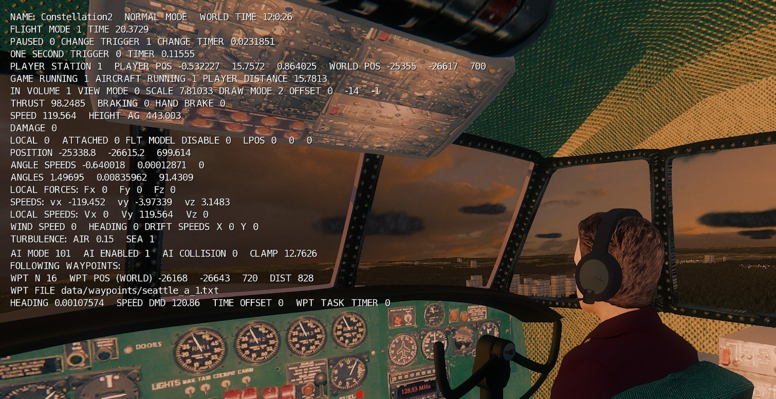
The image above shows a typical vehicle info display. In this example
the Constellation is following waypoints, so the vehicle info shows some useful
waypoint information including the current waypoint number and distance to the
next waypoint.
Normally vehicle info will be displayed for the nearest vehicle e.g. the
player vehicle. More specifically, the selected vehicle is the one nearest to
the player camera. For example, suppose you're driving a train. If you select
F6 external view and move your view close to the carriages in the train, you
can get the vehicle info for the carriages. By selecting a suitably large view
distance (PageUp and PageDown keys) you can even get vehicle info for distant
vehicles. To make this easier you can press the RH Alt key to pause *all*
simulator vehicles.
Two AircraftControl Properties settings directly control the vehicle
info display:
VehicleInfo: if enabled (checked) then the vehicle info will always be
displayed.
VehicleInfoName: if non-blank, vehicle info will be displayed for the
vehicle with the given name.
HUD
The full-screen HUD can be used to get essential
flight information from the forward cockpit view. There are two variations:
civil and military, as shown below.
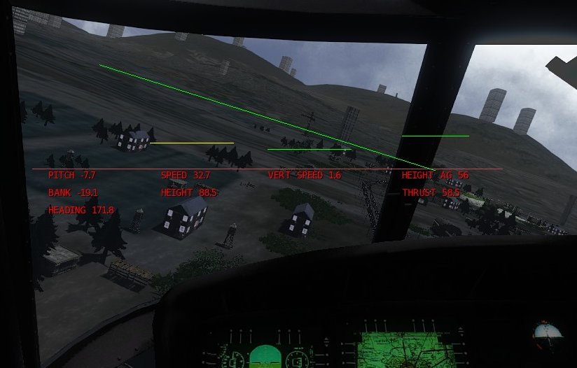
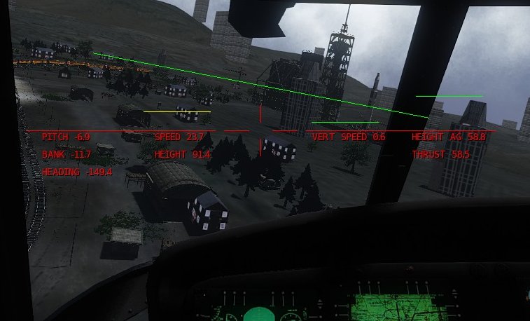
Currently the two variations are similar except that the military
version has a cross hair. The cross hair is useful for precision flight and can
also be used as an aiming sight for fighters.
The HUD is controlled by the H command. Each time you press H the HUD
will switch to the next mode: off, civil or military.
If you activate the HUD in the cockpit view then the HUD will be visible
only in the cockpit. If you activate the HUD in an external view then it will
always be visible.
You can set the HUD startup mode in AircraftContol Properties. Click HUD
to open a drop down menu and choose one option: Civil, Military or None.
The HUD displays the following variables:
Artificial horizon (pitch and bank)
Pitch, bank and heading (degrees)
Speed (MPH)
Vertical speed (meters/sec).
Height and Height AG (meters).
Thrust (percent).
COMBAT
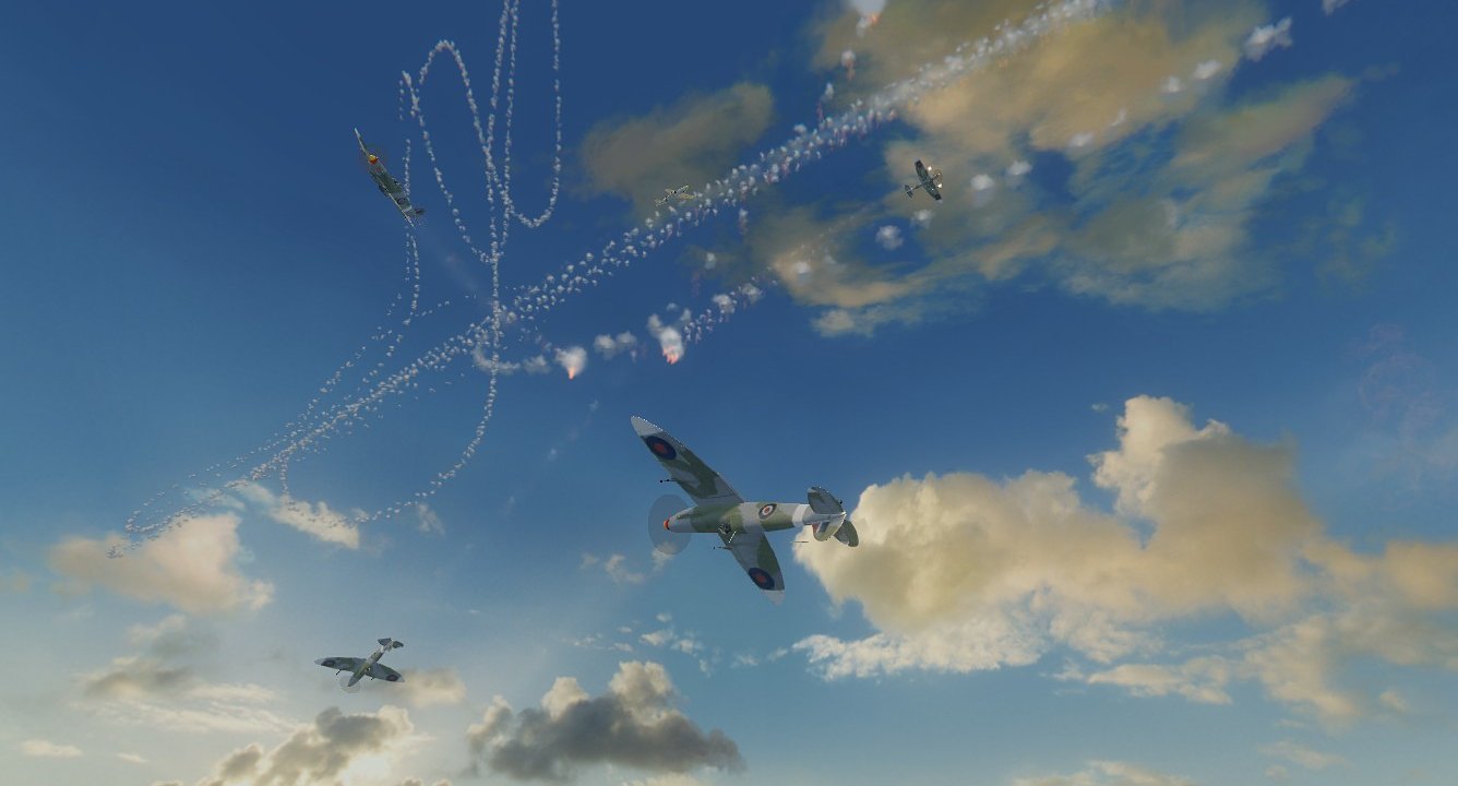
The simulator has full support for combat. When flying a fighter
you can strafe ground targets (e.g. buildings, ships or tanks) or you can
attack other fighters or bombers in the air. Available weapons are cannon,
bombs, torpedoes and guided and unguided missiles. Be warned: targets can shoot
back! The Heinkel and B-25 have fully functional gun turrets and positions in
AI mode and they will shoot you down very quickly unless you take evasive
action - or shoot them down first!
WEAPONS
All fighters have fixed cannon. Press CTRL-I (the letter i) to enable
the aiming sight. Alternatively press H to select the military HUD, which
includes an aiming sight. Press the mouse LH button to fire the cannon. You can
use the tracer to improve your aim. The cannon round entities use a unique
method to ensure clear visibility as long as they are in flight (in many games
tracer quickly becomes too small to be visible, so it can't be used for serious
aiming).
The LH mouse button fires the selected weapon, which defaults to cannon.
You can select your active weapon by pressing the W (Weapon) key. A message
indicates the selected weapon: cannon, bomb, or missile (torpedoes are treated
as missiles).
When attacking an aerial target, particularly a fighter, it can be very
difficult to control your speed, and very often you will overshoot the target
so the target is lost - and you're perfectly placed for the target to instantly
become the hunter! To overcome this problem you can use combat mode, which is
activated by the C (Combat) key. When you press C a message indicates the new
mode: normal, combat or formation flight. When combat mode is selected, you can
control your speed and thrust by pressing the RH and middle mouse buttons:
Faster: RH mouse button
Slower: press the middle mouse button.
If you're about to overtake your target, press the middle mouse button
to slow down. The controls are quite aggressive so, after a little practice,
you can quickly control your speed, which will make combat quite a bit easier.
These controls adjust the throttle, and also actively change the speed.
You can use combat mode to quickly move to another part of the map.
There is no limit to the speed increase. If you hold down the RH mouse button
for a few seconds you can achieve very high speeds e.g. 1000 mph or greater. If
you're about to go super-supersonic, press F1 to put the aileron and elevator
into neutral.
In the simulator, air-to-air fighter combat is quite realistic, and so
is very difficult. Aircraft are small and the sky is very big, and AI fighters
with your name on them can be deadly. Be prepared to be shot down regularly, at
least until you have gained plenty of experience. When shot down, your aircraft
will be uncontrollable and will start to spin. You can bail out by pressing key
O (for Out). Press O again (or space) to open your parachute, allowing you to
drift gently down to the ground.
To make your aircraft invulnerable (no damage), press key CTRL-H
(Health).
Selecting combat mode can help, as it allows you to control your speed
directly with mouse clicks, and this helps you to avoid overshooting your
target. You can also set up aircraft labels (in the AircraftControl Properties
rollup) and this makes it easier to find your prey. You can also set up
specified targets to show a simple red cross denoting your target.
Targeting command
When flying in an AI fighter aircraft, you can use the T (Targetting)
command to mark the current target aircraft. When you press key T, a message
will indicate the targetting mode:
1. "Show target label": the target aircraft is marked with a
red T.
2. "Track target": the aircraft is marked with a red T and the
player view keeps the target centered. This works particularly well for
external (spot) view.
3. "Track target, no label": the player view tracks the
target, but without the T label.
4. "Target label off": targetting disabled (normal mode).
CTRL-H command
To make combat a bit more user-friendly, there is a handy cheat command
which control the aircraft health:
CTRL-H: "AIRCRAFT DAMAGE DISABLED." This command makes your
aircraft invulnerable, and also clears any fire effects.
Note: you can monitor your aircraft damage by pressing the number pad
Enter key once. The text strip will indicate the damage value. A damage value
of 2 is fatal, and you will crash. You can press O (Out) to bale out and press
O again (or the space bar) to open your parachute.
GUN TURRETS
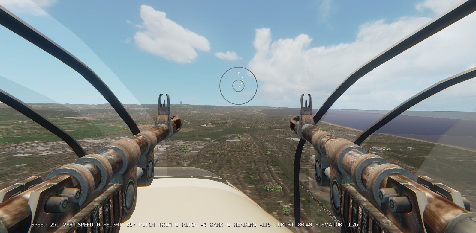
The Heinkel and B-25 are equipped with fully functional gun turrets and
positions. When occupying a gun station, simply move the mouse to aim (you will
see an aiming sight) and press the LH mouse button to fire. You can use the 6
key editing cluster (Home, End etc) to adjust your position. The aiming sight
automatically adjusts for player position changes.
Before accessing the gun positions, ensure you have selected combat mode
(not essential, but highly recommended). To go to the gun positions, press the
RH-SHIFT key. You are now in the first gun position. With combat mode enabled,
you can use the RH and middle mouse buttons to jump to the next or the previous
gun position:
RH mouse button: go to the next gun position
Middle mouse button: go to the previous gun position.
After some practice, you can quickly jump to the gun positions depending
on the current threat.
Ships and tanks also have gun positions which work in exactly the same
way.
Each gun turret or position can be individually set up in AI mode in the
aircraft Properties rollup. If you occupy an AI gun position then it will
automatically switch to manual mode. All unoccupied AI gun positions will fire
independently.
COMBAT KEY SUMMARY
Fire weapon: LH mouse button
Select weapons: W
Aiming sight: CTRL-I (letter i)
Select combat mode: C
Go faster: RH mouse button
Go slower: middle mouse button (LH mouse button
if formation mode is selected)
Go to gun positions: RH-SHIFT
Go to next gun position: RH mouse button
Go to previous gun position: middle mouse button
TRAINS
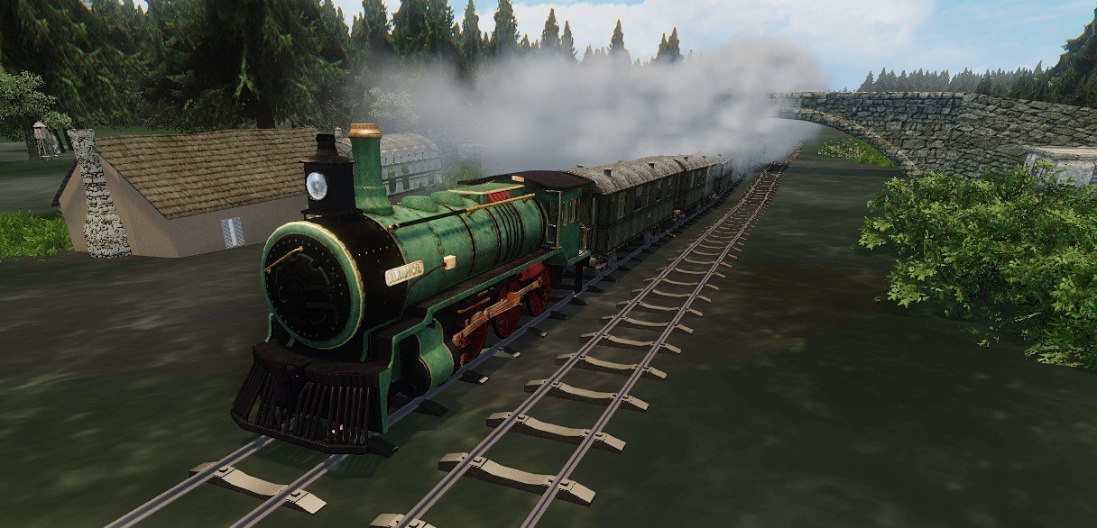
Many train functions are identical to aircraft functions. Some obvious
differences are that train vehicles are not steered, they can be coupled to
form trains and they don't have flaps and undercarriages.
The method of vehicle entry is identical: simply walk up to a locomotive
or carriage and, when the Press F to Enter message appears, press F. Unlike
aircraft, your start position in the vehicle (also selected by F1) will have
mouse view panning already enabled. You start the engines with the same CTRL-E
command and control the throttle with the plus and minus keys. Brakes are
controlled by the . key (full stop).
When any train vehicles are shunted together they are automatically
coupled to form trains (currently they can't be de-coupled). When forming
trains the F6 external view is very useful to see what's happening (press
PageUp to zoom out in order to give a wider view of the entire train).
All train vehicles have walk mode enabled. If you start in a carriage,
press F3 and LH mouse button to walk forwards. The walk commands are the same
as for aircraft. Note: carriages may not respond to the floor height function,
in which case the height adjustment command (mouse wheel roll) will not work.
You can walk between carriages. Currently you can walk through the
doors.
You can toggle the carriage lights on and off with the L command.
You can switch on/off all the lights in the train with CTRL-L
Other useful commands:
S (for Stop): Forces the locomotive throttle setting to
zero.
CTRL-B (for Brake): toggles the handbrake on and off. A
message indicates brake status. When the handbrake is set to on, all vehicles
in the train will also assert brakes on.
TRAIN PROPERTIES
Train vehicles have a set of special Properties settings, in the Trains
section, as follows:
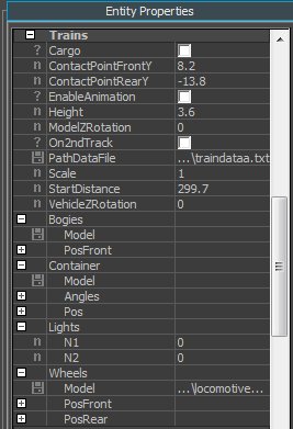
Cargo: Enabled if the vehicle is to carry cargo such as vehicles.
ContactPointFrontY: The y (forward) position of the vehicle front
bumpers. This is used when vehicles touch each other and form trains.
ContactPointRearY: The same as above, but for the rear bumpers.
Height: This allows the vehicle height to be adjusted so that it
correctly matches the rail tracks.
ModelZRotation: This sets the heading angle of the vehicle model
with respect to the entity. Normally zero, but allows vehicle models to be used
that do not conform to the normal y forwards standard.
On2ndTrack: If enabled, the vehicle will be placed on the second
parallel track.
PathDataFile: Path to the train data file e.g.
data/trains/trackdata/seattle_train_data.txt
StartDistance: This sets the default distance along the track
(position), in meters. A value of zero would place the vehicle at the start of
track 1. If you drag the value you will see the vehicle moving.
StoppingDistance: trains automatically stop when they approach the end
or beginning of the track. This setting determines at what distance from the
start or end of the track deceleration will start. A setting of a few hundred
meters will give a gently stop, while a value less than one meter will give a
hard stop as if running directly into the buffers.
VehicleZRotation: This rotates the vehicle horizontally (heading). If
the vehicle is on the second track then normally the setting would be 180
degrees, otherwise zero.
If you want to place a cargo brush e.g. on a flat bed carriage, you can
use the Container settings. Enter the path to the model .cgf file, and set the
position x,y,z values, and also the x,y,z angle values (in radians)
If you start with a small number of locomotives/carriages etc, the best
way to create more vehicles to form a train is to make copies. After making a
copy, set the Properties Trains -> StartDistance setting of the copy to
define its default start position on the track.
Bogies: This sets the path of the bogie model and also the x,y,z
position of the front bogie. The rear bogie is placed symmetrically at the rear
(the y value is equal but negative).
Wheels: This sets the path of the wheel model, and also the x,y,z
positions of the forward and rear wheels (with respect to the bogie).
The editor is used to create and edit new rail tracks. This release
includes an in-game tutorial on how to use the editor. After editing, the track
layout is saved to a data file. The data file is used by train vehicles and the
railtrack autogen.
Each rail track is created by one instance of the RailtrackObjects
entity. The objects displayed by the entity are:
1. The main track and a second parallel track.
2. Overhead power cables (optional, set by the OverheadCables Properties
setting).
3. Continuous tunnel model when track is below the terrain.
4. Random bridges crossing the track.
5. Semi-random pre-made groups of objects (a group file) e.g. a station,
including platforms, buildings and people.
6. Autogen objects and effects. When new tracks are added as the train moves
forwards, a set of associated autogen objects are also added, typically within
a few hundred meters of the track. A data file specifies which objects will be
used, together with parameters such as object density (number of objects),
minimum and maximum distances from the tracks.
The number of tracks are set by the RailtrackObjects Properties TotalN
setting. For a typical setting of 50, 25 tracks wil be shown in front of the
train, and 25 behind. The number of autogen objects per track is set by
MaxObjectsPerTrack (typical value 15). To increase frame rates, reduce either
or both settings.
Because all tracks and objects are placed and removed dynamically as the
train goes along, tracks can be extremely long without impacting frame rates.
In one test the track was a little over 100 km long, and there was no obvious
limit. It took around one hour to complete the journey. Quite possibly a 1000
km track could be built without any performance degradation.
The Properties TrackObjectsFolder setting allows different sets of
tracks to be used e.g. tracks with gravel and without. Each set of tracks have
the same standard .cgf names and they are placed in different folders. If the
specified folder contains road models then a road will be generated.
TRAIN VEHICLE TYPES
As described above, each locomotive or carriage vehicle can be assigned
a different main model in their Properties settings. Other Properties settings
can radically change the vehicle's appearance e.g. by changing the models and
positions of the bogies and wheels, and adding cargo models. For this reason
there is a fairly small range of vehicle entity types, as follows:
LocomotiveA: the standard locomotive type.
LocomotiveSteam: a locomotive with smoke effects and animated pistons.
CarriageA: a carriage which has additional seat models and animated
doors.
CarriageC: the basic carriage which has a single model, and no
additional objects such as seats, and no animated doors.
TrainGun: a carriage with a mounted gun.
Group files can be used to conveniently import train vehicles already
set up in another map, as follows:
1. In a map containing some train vehicles e.g. the Seattle demo map, select
some vehicles as required and export them to a group file (from the top Modify
/ Save Objects.... menu).
2. Load the group file into a new map and move the vehicle pivots so they're
close to the track where they will be placed.
3. In each vehicle, set the path to the track data file (Properties / Trains /
PathDataFile). When you click Reload Script the vehicle will jump to its set
position on the track.
4. Set each vehicle's position on the track (Properties / Trains /
StartDistance, drag the slider and the vehicle will move along the track).
5. To add more vehicles, make copies and adjust the StartDistance setting for
each copy.
MULTIPLE TRACKS AND BRANCHING
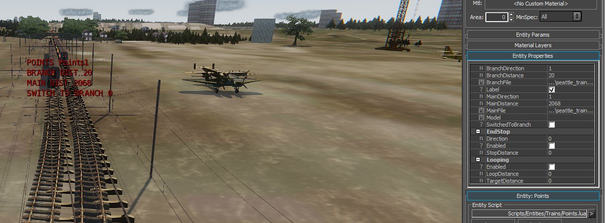
You can have any number of separate tracks, each one controlled by an
instance of the RailtrackObjects entity. One track can be joined to another,
thus creating branch tracks. Branching between lines is controlled by the
Points entity. A Points entity is placed close to the junction and its
Properties set up as required. Before discussing these functions in detail,
it's important to define the terms which will be used.
DEFINITION OF TERMS
Junction: a point where two tracks meet and where branching can occur.
One track is the main track and the other is the branch track.
Main and branch track:
At any junction, the branch track is the one that either starts or
ends at the junction. The main track is the one that passes through the
junction.
Note that it�s not absolute: at one junction
the track may be the branch track, but at another junction the same track may
be the main track.
Direction of travel (indicated by +1 or �1)
When moving in the forward direction (indicated by +1), the track number
and distance increases.
When moving in the backward direction (indicated by
-1), the track number and distance decreases.
For example, in the Seattle game one scenario, you are in a moving four
carriage train. Press number pad key 3 to display the train info. You will see
that both the distance and track number values are
increasing. You are therefore moving in the forward direction, indicated by +1.
As train vehicles follow a specified
track, their positions are set by one value: the distance along the track,
measured in meters (the variable self.distance). At the start of the track the
distance is zero (but default vehicle positions, set in vehicle Properties,
should be larger than zero, typically 20 or 30 meters). When in a train
vehicle, you can enable train info by pressing number pad 3. The train info
shows both the track distance and track numbers.
HOW BRANCHING WORKS
When a train vehicle approaches a
junction, and when it is sufficiently close to the Points entity, the two
entities communicate. If the driver has not used the B (Branching) command to
override the Points settings, the action taken by the vehicle will depend on
three things:
1. Whether the vehicle is on the main or the branch track.
2. The vehicle's direction of travel (+1 or -1).
3. The Points Properties SwitchToBranch setting (can by over-ridden by the B
Branch command).
Suppose the vehicle is on the main track, moving in the positive
direction, SwitchToBranch is enabled, and both Points direction settings are
+1. The vehicle will therefore switch to the branch line. When the vehicle
reaches a defined position on the main track, it will switch to a defined
position on the branch track.
Each train vehicle gets the train track data from a file whose path is
set by the vehicle's self.TrackFile variable. When on the main track the path
defines the data for the main track. When the switch occurs, the Points entity
writes a new path to self.TrackFile. The path now defines the data for the branch
track, and the vehicle will therefore follow the branch track.
The switch positions for the main and branch track (more specifically,
the distance values in meters) are set by the Points Properties. To get a
smooth transition, the Sandbox x,y,z positions corresponding to the two
distance settings must be equal, and the track angles must also be equal.
Each vehicle in the train will follow the same procedure so that the
train will remain intact when switching to a branch track.
The decision whether to switch to the branch line or not can be set in
two ways. First, as mentioned previously, the SwitchedToBranch Properties
setting of the Points entity determines this, rather like track points in the
real world. The second method allows the train driver to make the decision,
rather like a remote control.
When driving a train, press number pad 3. Several lines of useful train
data will appear in the top left of the screen, including the distance along
the line, the track number and points switching status. One line indicates the
points switching status. It will start in neutral mode, with switching set by
the Points entity. Press key B (Branching) to change the mode. The next
mode will override the points and force the train to stay on the main line. The
final mode (press B twice) will override the points and force the train to
switch to the branch line. Press B again to return to neutral mode (branching
set by points).
POINTS
PROPERTIES SETTINGS
BranchDirection and MainDirection:
At any junction, imagine you are moving along the main track and then
branch onto the branch track.
If you were moving along the main track in the forwards direction (+1)
then MainDirection should be set to +1, otherwise �1.
After switching to the branch track, if you�re moving in the forwards
direction (+1) then BranchDirection should be set to +1, otherwise �1.
In short, the two direction settings represent the initial and final
movement directions when you switch from main to branch track.
BranchDistance: When switching from a main track to a branch
track, this sets the target position (distance) on the branch track. When
switching from a branch track to a main track, this sets the position on the
branch track where the switch will occur.
BranchFile: the path to the track data file for the branch
track.
Label: if enabled, a label is placed on the Points entity, as shown in the
picture above. It displays the points entity name, the main and branch distance
settings, and the SwitchToBranch setting.
MainDistance: When switching from a main track to a branch track, this sets the
position on the main track where the switch will occur. When switching from a branch track to a main track, this
sets the target position on the main track.
MainFile: the path to the track data file for the main
track.
Model: Visible brush model for the Points entity, usually left blank.
SwitchToBranch: If enabled, the train will switch to the branch line. It's the
equivalent to how points are set in the real world. The B (Branch) player
vehicle command can be used to override this setting.
END STOP SETTINGS
These settings enable the Points entity to work like real world train buffers.
Direction: the vehicle movement direction that will trigger the end stop
function.
Enabled: enables the end stop function.
StopDistance: sets the distance at which the end stop function will be
triggered.
LOOPING SETTINGS
These settings enable trains to jump from one part of the track to another,
usually used to enable circular tracks.
Enabled: enables the looping function.
LoopDistance: sets the track position where the vehicle will jump back to the
start of the track.
TargetDistance: the track position that the vehicle will jump to.
AI TRAINS
Train vehicles (e.g. a locomotive) can work in AI mode by following
waypoints. The locomotive is set up in a similar way to an aircraft by its
Properties: select FollowWaypoints and set the path to the waypoint file. When
creating the waypoint file (e.g. with the simulator editor) ensure that each
waypoint is close to the track (no more than two meters away).
You can control the train by using the StopTrain waypoint command. The
first parameter sets the stopping distance in meters. The time parameter sets
how long the train will stop before starting again (the time includes the time
needed to stop).
SHIPS AND SUBMARINES
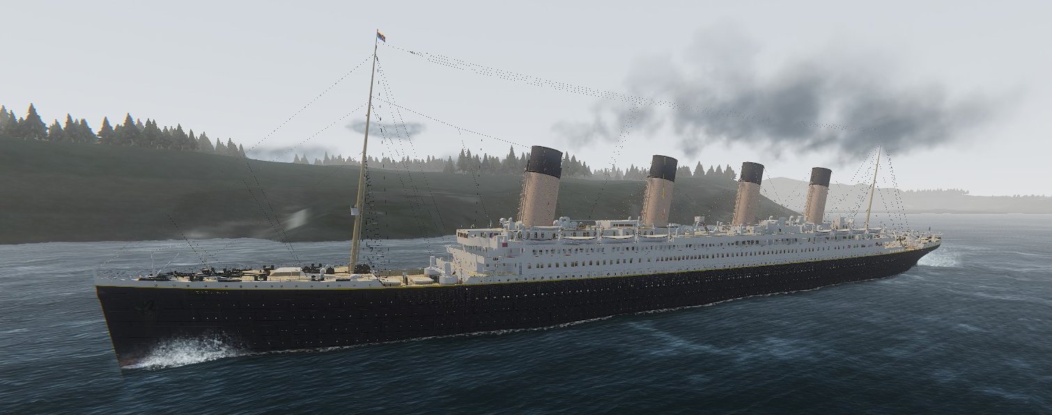
Many ship functions are similar to other vehicle functions, but there
are some differences.
Ships (e.g. Titanic and the aircraft carrier) have a defined volume that
will include the deck space and may also include the interior, as with the
Titanic. If the player is inside the volume when he presses F to enter, he will
immediately be placed into walk mode at the same location. For example, to
start on the rear deck of the Titanic, in editor mode move the view close to
the deck, then start game mode and press F. You will be placed in walk mode on
the deck. You could also start in the Titanic's detailed interior.
Press F1 to go to the bridge (the engines can be started only from the
bridge and not in walk mode). Press CTRL-E to start the engines and press
the plus key to increase the power. Titanic will steam ahead. Press F3 to
return to the deck in walk mode.
The Titanic has a detailed interior but no working doors. In order to
walk from the decks to the interior, you can use a special command: key 1
(one). Press and hold down key 1. You will walk forwards through any solid
obstacles such as walls or non-functional doors.
You can also use aircraft or other vehicles on the decks of a ship,
usually an aircraft carrier. To make aircraft follow the movements of the ship,
ensure the aircraft's Properties.AI.Mode.AutoRun setting is checked.
If you are in walk mode on a ship's deck you can enter an aircraft on
the deck in the usual way: when the press F to enter message appears, press F
and you will be transferred from the ship to the aircraft. Even if the ship is
moving and turning, you can taxi the aircraft and take off and then land again.
You can try this with a demo map that has B-25's on the deck of the aircraft
carrier. You could place the BlackHawk helicopter on the Titanic's deck and
take off and land when the Titanic is under way.
Aircraft can also work in AI mode on the ship's deck. When taxiing on
the deck the waypoint file must use coordinates local to the ship, and then
switch to world coordinates at the point when the aircraft takes off. Aircraft
can take off from a ship in AI mode but currently they cannot land.
Ships can be fitted with gun turrets or positions in exactly the same
way as aircraft (e.g. the aircraft carrier and submarine). Press C for combat
mode, press SHIFT key to go to the first gun position. Press mouse RH and middle
buttons to move between the gun positions.
![]()
Submarines are essentially the same as ships, but with one important
difference. In aircraft the player can roll the mouse wheel to adjust pitch
trim. For a submarine, the mouse wheel is used to control the ballast. To
submerge, roll the mouse wheel backwards, and to return to the surface, roll
the wheel forwards.
In addition to guns, you can fire torpedoes. Press M (Missile) to fire a
torpedo (torpedoes are treated as missiles). Or press W (Weapon) to select
missiles, and fire by pressing the LH mouse button.
HELICOPTERS
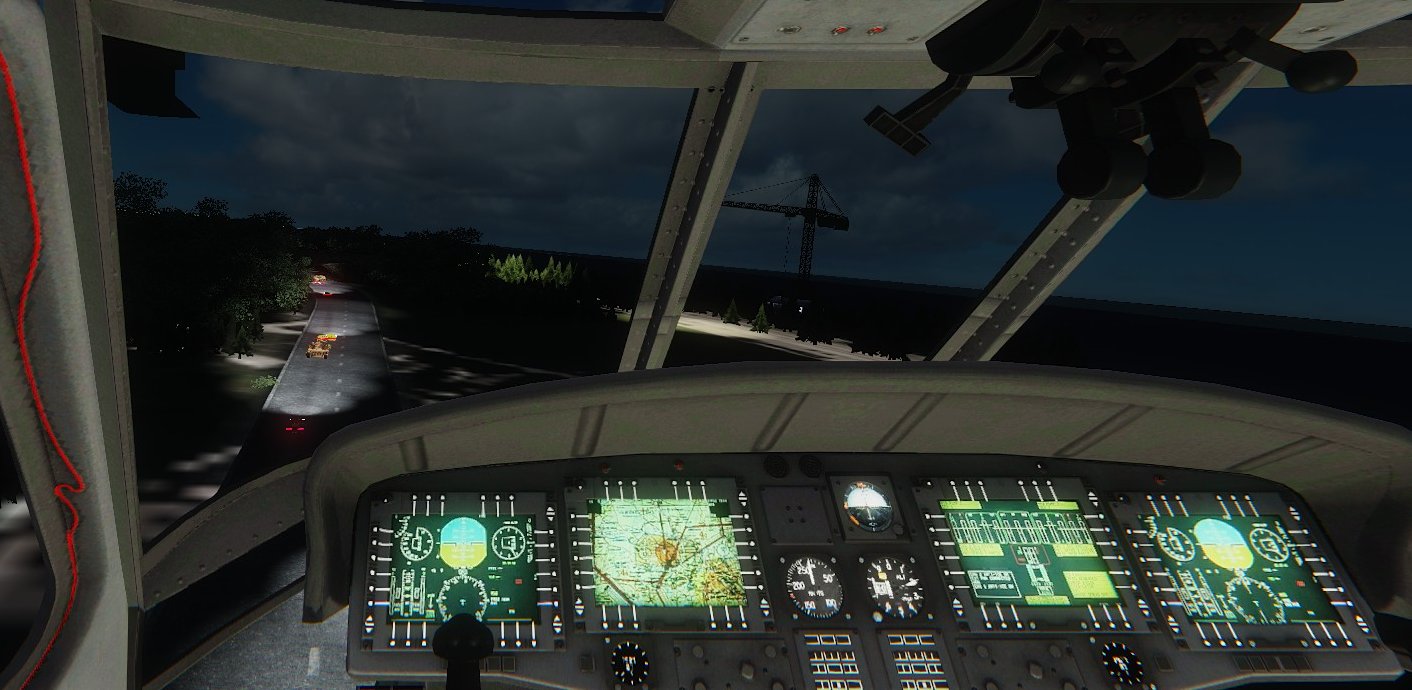
For hovering control, accurate and convenient throttle
control is important. There are several methods:
1. Use the plus and minus keys.
2. Roll the mouse wheel.
3. In normal mode, press the LH and RH mouse buttons (RH to increase).
In combat mode (key C to select), press the middle (wheel) and RH mouse
buttons.
HUD
The simple full-screen HUD is particularly useful when flying and landing
helicopters.
To enable/disable the HUD, enter the command H
The pitch, forward speed and vertical speed are indicated by coloured
lines. The longer pitch line also indicates the bank angle.
A line moving upwards indicates an increasingly positive value. When
about to land the yellow and green lines (forward and vertical speed) should be
close to the base line.
You can pitch the helicopter forwards/backwards with the mouse, even
when hovering. Pitch forward to increase forward speed and vice versa.
VTOL (HARRIER)
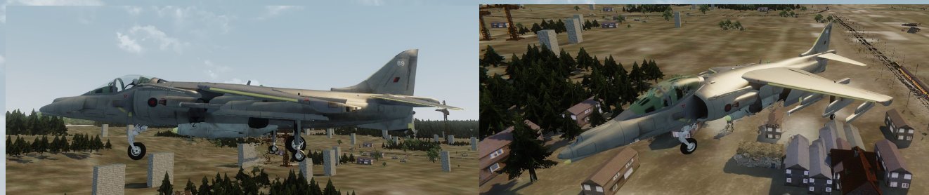
The simulator includes a Harrier GR5 jump jet, with full
VTOL support. Flight control is similar to that for helicopters (see section
above). But there is one important difference: the engine thrust can be rotated
from vertical to horizontal (tilt angle). The tilt angle is controlled by
rolling the mouse wheel while pressing the LH Ctrl key. When adjusting the
angle a message indicates the current tilt angle. Tilt angle is also indicated
by the on-screen HUD (key H to activate).
In normal mode, control the engine thrust by pressing the LH and RH
mouse buttons, or by rolling the mouse wheel. In combat mode (press C to
select) control the engine thrust by pressing the middle (wheel) and RH mouse
buttons, or by rolling the mouse wheel. In hover mode, control the forward
speed by controlling the aircraft pitch (pitch down to increase speed). With
zero tilt angle, the Harrier will fly as a normal aircraft.
QUICK HARRIER TUTORIAL
1. Load the Seattle demo map.
2. In game mode, walk to the Harrier and press F to enter.
3. Press CTRL-E for engine on.
4. Press F6 for external view and watch the jet nozzles below the wing.
Initially they point vertically down (90 degree tilt angle).
5. Hold down the LH Ctrl key and roll the mouse wheel backwards. You will see
the jet nozzles rotating and the screen message confirms the tilt angle is
changing.
6. Select a tilt angle of 85 degres. Because the Harrier sits with an
approximately 5 degree positive pitch, a 90 degree tilt angle will generate
some reverse force which may make the Harrier roll backwards.
7. Press H twice to enable the military HUD. You will need to watch the
vertical speed indicator very carefully.
8. Press the RH mouse button to increase power (or roll the mouse wheel
forward).
9. With an indicated thrust of just over 50% the Harrier will take off
vertically. In external view you will see the vertical heat plumes from the
four jet nozzles.
10. Press F1 for cockpit view. While hovering, control forward speed by controlling
the pitch (move the mouse gently up and down as required).
With some practice you should be able to achieve accurately controlled
hovering flight.
11. To transition to normal forward flight, press LH Ctrl and roll the mouse
wheel to select a zero tilt angle. As the tilt angle reduces, ensure you have
sufficient forward speed to provide the required lift.
SPACEFLIGHT
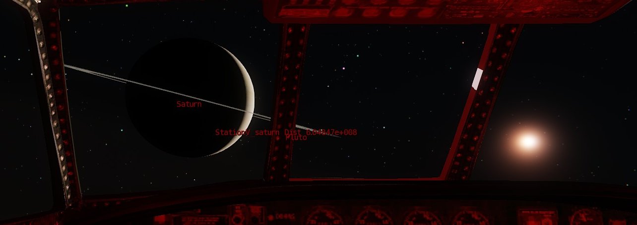
The simulator includes a unique spaceflight system that allows orbital
flight around planets and journeys between the planets. A spacecraft control
mode is provided so that a spacecraft can be moved and rotated in any
direction. Spacecraft can be controlled realistically by operating the main
engine. In addition a 'super control' system is available to make things easier
e.g. to provide thrust equivalent to thousands or millions of times stronger
than real-world engines, particularly useful if you only have ten minutes or so
to complete a journey to Mars.
The simulator creates the entire solar system by offsetting and scaling
spacecraft, planets and moons, so that all the planets can be packed into
Sandbox. The code controls the scale of planets and moons so that they always
have the correct apparent size.
The spacecraft entities share common code with the aircraft code, with
additional code to handle spaceflight. The solar system is implemented with
three Lua entity types, SolarSystemB, Planet and Terrain. In addition to having
overall control of the planets, SolarSystemB also controls spacecraft functions
where spacecraft interact with planets. Each planet or moon is an instance of
the Planet entity, which controls specific planet functions. The Terrain entity
controls the detailed terrain when the player is on a planetary surface.
There are three spaceflight demo maps in the Space section:
1. Spaceflight_orbit: in the Orion spacecraft in Earth orbit.
2. Spaceflight_orbit_tutorial: as above, but with the spaceflight tutorial
enabled. It shows how to control the spacecraft and takes you on a voyage to
Saturn.
3. Spaceflight_surface: places you on the surface of Earth. Press BACKSPACE and
then press a number key to run the saved games. When in the Apollo command
module you can use the key commands: 2 to fire Saturn booster, 3 to shut down
booster, 4 to drop booster, then repeat the sequence for the next booster.
Note: the detailed planetary surface system is still under development.
When you're ready for your first spaceflight, load the Spaceflight_orbit
map (in the Space section).
Before flying a spacecraft, you can take a quick tour of the solar
system in editor mode, as follows:
1. Use the Goto Position button at the bottom of the Sandbox screen to
set your position to the origin (0, 0, 0).
2. In the selection box, select the SolarSystemB entity and click Reload
Script. You will notice some planet labels but you may not see a planet just
yet.
3. In the SolarSystemB entity rollup, select PlayerPos and increase the R value
to around 10. When you scan around you should now see the Earth. Reduce R to
move closer. You can adjust the Latitude and Longitude Properties settings to
change your view of Earth.
4. You can now jump to the other planets. The SolarSystemB PlanetN Properties
setting defines the planet. Earth is number 5. Change it to 6, click Reload
Script and you should now see the moon. Increase the number, click Reload
Script, and you will see a succession of planets and moons. When you set 13
you'll see Saturn, complete with its rings and four largest moons.
5. Increase the R value until you can see the four largest moons of Saturn.
Click (check) the Properties Enabled box and in SimRate.Rate enter 9999. When
you click Reload Script, you will now see the moons circling around Saturn.
Note: before taking a flight you should disable these settings: uncheck Enabled
and set the sim rate back to 1.
Now we're ready for our first spaceflight. With the Space map loaded and
with default settings, press CTRL-G for game mode. In a few seconds you'll find
yourself in the cockpit of the Orion spacecraft in orbit around Earth, together
with a collection of other spacecraft and the 2001 space station (Station V).
You'll find that some of the standard aircraft commands to control your
view still work for spacecraft: F1 for cockpit, F2 for cockpit with mouse
panning, F6 for external view. Press L to toggle the lighting.
You'll notice that, although you're a few hundred miles above the
Earth's surface, you are actually close to the Sandbox origin (0, 0, 0). When
in space your spacecraft stays at the origin and all the other spacecraft and
planets move and are scaled as required to maintain the illusion of the
vastness of space.
SPACECRAFT CONTROL MODE
To enable spacecraft control, press the left Ctrl key. The message
"Spacecraft control on" will show. When spacecraft controls are
enabled, some keys are assigned to new functions, as follows:
Engine thrust:
Forward and reverse thrust: up and down arrow keys.
Sideways thrust: left and right arrow keys.
Up and down thrust keys: PageUp and PageDown.
Rotation (number pad keys):
Sideways rotation (heading): number pad left and right arrow keys (4 and
6)
Up/down rotation (pitch): number pad up and down arrow keys (8 and 2).
Roll rotation: number pad keys 7 and 9
Stop rotation: number pad key 5.
To increase or decrease the thrust strength, press the number pad * and / keys
(multiply to increase, divide to decrease, each press multiplies or divides the
thrust by a factor of ten).
To get fine thrust, press number pad / until the message indicates a
thrust multiplier of 1 or even 0.1 for very fine control. On the other side of
the scale there's no limit, so you could press * a few times to get one million
or even higher. A value of ten million might be a good value to make a very
quick trip to the moon.
Here's a quick tutorial to get you to the moon in five minutes:
1. In the Orion spacecraft, press the left Ctrl key to activate spacecraft
control. A message will confirm whether it's enabled or disabled.
2. Press F6 for external view and identify the moon's location (it will be
approximately behind the Orion).
3. Press number pad left key to start rotation to the left.
4. Press F1 for cockpit view and wait for the moon to come into view. When it's
in view press number pad 5 to stop the rotation. Then carefully use the number
pad arrow keys to roughly center the moon in your view. When it's centred,
press number pad 5 to stop rotation.
5. Press number pad 3 until the solar system info is displayed: it shows
information for Earth and the moon. In particular, it shows the distance to the
moon.
6. Press the number pad * key to get a multiplier of ten million (1E7).
7. Carefully press the up arrow key for forward thrust. Your speed will
increase dramatically and you should soon see that the moon distance is
falling. If you quickly hit F6 for outside view, you will see the Earth rapidly
falling back. Hit F1 for cockpit and watch the moon distance (and the moon,
just in case). When you've reduced the distance somewhat and you can see the
moon moving, hit number pad / to decrease the multiplier, to get finer control.
Press the down arrow key to reduce forward speed. If the moon drifts upwards,
hit PageUp for vertical thrust, and PageDown if the moon drifts down.
Similarly, if the moon drifts sideways, use the left and right arrow keys to
compensate. Be ready to hit number pad / to continuously get finer control as
you approach the moon.
Tip: if you think your voyage to the moon is about to go pear-shaped,
press key Q to save the game. At any time you can press key R to recall
the saved game, so you can start each time without having to align the Orion on
the moon.
As you approach the moon, reduce the multiplier and reduce your forward
speed. With a bit of luck you'll achieve a lunar orbit.
You could also make a flight to the moon much more realistic by using
the normal engines. Start by aligning the Orion on the moon as in the tutorial.
But, instead of using the magic up arrow key, type in CTRL-E to start the
engines and then press the plus key to increase thrust to full. In external
view you'll see the other spacecraft disappear into the distance, but you won't
see your forward motion compared to the Earth for a while. However, you will
see that the moon distance is starting to get smaller. If you shut off the
engine after one minute you'll be going at around 50,000 miles an hour, so you
should reach the moon in 5 hours, considerably faster than the Apollo
spacecraft.
You can perform EVA's as follows:
Press left Ctrl to enable spacecraft control and press F3 for walk mode
(float mode might be a better name!) Of course, as you're in space walk mode
will work a bit differently compared to aircraft. You will be placed in the
Orion cabin (which looks strangely similar to the Constellation cabin). You can
use the now hopefully familiar number pad arrow keys to control your rotation,
and the arrow keys to control your movement. In fact, the EVA controls are
exactly the same as the spacecraft controls e.g. up arrow for forwards.
Carefully rotate until you're looking at the front of the passenger
cabin and press up arrow to slowly move forwards while aiming for the open
door. When you attempt to float through the open door, your motion may stop,
possibly due to a bug. If this happens, press key 1 to move forwards (this
command ignores solid sirfaces such as walls). When you're clear of the Orion
you really are in space!
GROUND VEHICLES
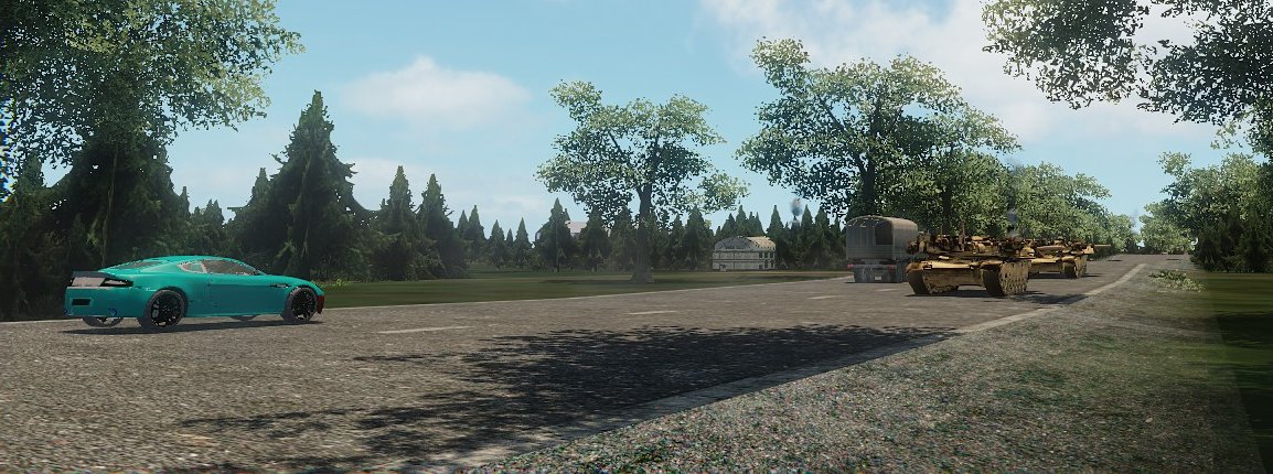
Ground vehicle types include cars,
trucks and tanks. Vehicles included in this release are the Abrams tank, truck
and the Aston Martin.
Many ground vehicle functions are the same as for aircraft, e.g. press F
to enter and CTRL-E to start the engine. They can operate in AI mode e.g. to
follow waypoints just like a taxiing aircraft. If a gun turret is attached to
the vehicle it can operate in AI combat mode e.g. the Abrams tank.
To use the tank
in combat:
1. Approach the tank and press F to enter.
2. Press CTRL-E to start the engine.
3. Press C to select combat mode.
4. Press mouse RH button to accelerate and mouse middle button to decelerate,
and move the mouse to steer.
5. Press RETURN to enter the gun turret. You will see an aiming circle.
6. Move the mouse to aim the gun and LH mouse button to fire.
AUTOGEN
Autogen is a system that dynamically places scenery elements on the
terrain. Because objects are placed and then deleted as the player moves across
the map, there is no limit to the size of the map and good frame rates are
achieved, even for a map that effectively has millions of objects.
Autogen comes in two flavours: general autogen and railtrack autogen.
General autogen (in future referred to as 'autogen') covers complete
squares of terrain, and so is ideal for flight simulation. With default
settings the autogen fills a square 25 km across and centred on the player
location. As the player moves or flies across the map, objects in 5 km
sub-squares which fall behind the 25 km main square are deleted (more
specifically, the entity slots that held the objects are freed). The slots for
this sub square are then available for when new sub-squares need to be placed
in front of the player.
Railtrack autogen does not fill squares of terrain. It places objects
along rail tracks. Like general autogen, it deletes objects that fall behind
the train and re-uses the slots to place objects ahead of the train. Even if
the rail track is 100 km long, the railtrack autogen ensures that the traveller
will see lots of dense scenery passing by. Both general and railtrack autogen
can be used together.
GENERAL AUTOGEN
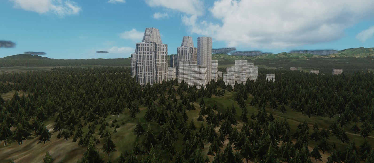
The autogen system uses two Lua entity types: ObjectsControl and
ObjectsSpawner. You can think of ObjectsControl as the conductor while the 25
ObjectsSpawner instances are the orchestral players.
When the map is loaded, ObjectsControl will spawn 25 instances of the
ObjectsSpawner entity. The job of each ObjectsSpawner is to fill its local 5 km
sub-square with objects on the terrain.
In effect ObjectsControl constructs a main square 25 km across and
centred on the player. The main square only moves in 5 km steps and its
location x,y values are multiples of 5 km. The entity ensures that each of the
25 sub squares has an ObjectsSpawner entity placed in it. The main square is
placed so that the player is always in the central 5 km square.
Suppose the player moves east. When he leaves the central 5 km square,
ObjectsControl will jump into action. First it will move the main square to the
next position, which is 5 km to the east. It will then free the objects slots
for any sub-squares that are now outside the main square (to the west). It then
moves the ObjectsSpawner instances which have just been deleted to the east, in
order to maintain a complete main square centred on the player. After moving
the entity, it sends a command to create new objects. This process continues as
the player moves around the map.
Two files control the object layout, types and density.
The first is a 256 colour bitmap e.g.
GameSDK\Data\Autogen\Objects_Seattle.bmp
Each non-black pixel defines an object type which will be placed at that
position. You could manually paint a bitmap to create towns, cities, plains,
forests etc. The size of the terrain square covered by the bitmap is
configurable via the Properties setting, but the default is 80000 (80 km). The
bitmap therefore defines the objects for a terrain square 80 km across. If the
player moves outside the 80 km square (centred on the Sandbox origin) then the bitmap
is repeated, so that points 80 km apart will have the same objects. The default
bitmap size is 1024*1024, and they define around one million objects. Other
bitmap sizes can be used, but they must be square and the size a power of 2
e.g. 256 or 512. I did test a 2048*2048 bitmap, but performance was not good.
The second file is a text data file that defines the actual object types
and their parameters e.g.
GameSDK\Data\Autogen\Objects_Seattle_water.txt
An example:
TYPE ENABLED
DENSITY RANDOM OFFSET Z AREA SIZE
X Y SIZE MIN/MAX OBJECT HEIGHT
MIN/MAX
OBJECT FILE PATH
Object Brush, 1,
0.2, 1, 0,
0, 5000,
5000, 0.3, 1.2,
106, 800,
Objects/Autogen/TreeX/XtreeA/trees3.cgf,
,
Object Light, 1,
1.5, 0, 5,
0, 5000,
5000, 100, 200,
111,
1000,
, ,
Object Brush, 1,
1, 0, 0,
0, 5000,
5000, 2, 8,
111, 350,
objects/buildings/testbuildings/buildingtestc.cgf,
,
Object Brush, 1,
1.4, 0, 0,
0, 5000,
5000, 2, 8,
111, 3500,
Objects/Buildings/TestBuildings/Texture1/buildingtestd.cg, ,
Object Effect, 1,
2, 0, 1,
0, 5000,
5000, 2, 5,
111, 1000,
smoke_and_fire.fire_small,
,
Object Cloud, 1,
0.25, 1, 10
0, 5000,
5000, 70,
150,
0, 1000,
Spitfire.runway_light.fake_lights_red,
,
Object Group, 0,
1, 0, 0,
0, 5000,
5000, 1, 1.2,
111, 800,
Scripts/Entities/Aircraft/Data/Houses_E.grp,
,
After the 'Object' keyword, the parameters are:
Type, e.g. Brush, Light, Effect, Cloud, Group.
Enabled: values are one if enabled, zero if disabled. If disabled, the object
will not be placed.
Density: controls the number of objects placed, values in range zero to
one. More specifically, the value sets the probability that the object will be
placed in each position.
Random: A value of 1 enables x,y position randomisation, particularly
suitable for trees.
OFFSET Z: adds a vertical offset, in meters
AREA SIZE X Y: sets the size of the sub-squares, default is 5000 (5 km).
(The sub-square size is now set in the entity Properties, so these settings are
obsolete).
SIZE MIN/MAX: Sizes are randomly chosen in the min/max range. A value of
one corresponds to the object's default size.
OBJECT HEIGHT MIN/MAX: Objects will be placed only if the terrain height
is within the min/max range. Set the min value slightly larger than the water
height to ensure houses are not placed in the water.
OBJECT FILE PATH: Defines the path to the object e.g. file path and name
of a brush, a group file or effect type
The colour index of each non-black pixel in the bitmap defines the object
type. A pixel index of one will correspond to the first entry in the data file,
an index of 2 will correspond to the second entry, and so on. It's a good idea
to leave a blank line after every ten entries, as this makes it easier to count
down to get the corresponding pixel index value.
The ObjectsControl entity has a number of Properties settings, as
follows:
AreaSize: sets the size of the sub-squares. Default value is 5000 (5
km).
BitmapPath: the path to the bitmap, normally placed in GameSDK\Data\Autogen
BitmapWorldSize: sets the size of the terrain square covered by the
bitmap (the bitmap is centered on the Sandbox origin). Defalt value is 80000
(80 km).
DistantAutogen: enables distant autogen (a relatively small number of
objects placed at much greater distances).
GlobalDensity: sets the overall object density, in the range zero to
one. The default is 0.5, but if frame rates are low, a value of 0.1 or 0.2
could be used.
NumberOfSlots: this sets the maximum number of objects generated by each
instance of ObjectsSpawner. Typical value: 3000.
ScriptPath: the full path to the text data file, normally placed in
GameSDK\Data\Autogen
ShowInfo: if enabled, will show some debug info in the top left of the
screen (in game mode). VISIBLE OBJECTS indicates the approximate number of
objects visible in the camera view. A log will also be shown in the centre of
the screen when objects are being updated.
ShowSpawnedEntities: if enabled, the entity will place a sphere at
the position of each instance of ObjectsSpawner. It also displays a label that
gives the name, position and number of objects.
When the map is loaded, the ObjectsControl entity will load the text
data file and the bitmap, and then copy the data into two tables. It will then
spawn 25 instances of ObjectsSpawner, and it passes copies of the tables to
each one. When commanded to create new objects, each ObjectsSpawner instance
scans across part of the bitmap that corresponds to its local sub-square. After
getting the pixel index, it looks up the table to get the object parameters
such as object type and size. It then uses RayWorldintersection() to get the
terrain height, and then places the object. Because this process is
CPU-intensive, it distributes this process over multiple frames. It takes
around a minute to update the objects for all 25 entities.
You can easily create new autogen bitmaps and data files, or edit the
existing ones. When editing the data file, ensure you keep precisely the same
format. In particular, every parameter must be followed by a comma, and the
number and layout of commas must be exactly as in the example above.
When in-game, you can enter the keyboard command X to reset and reload
the objects.
RAILTRACK AUTOGEN
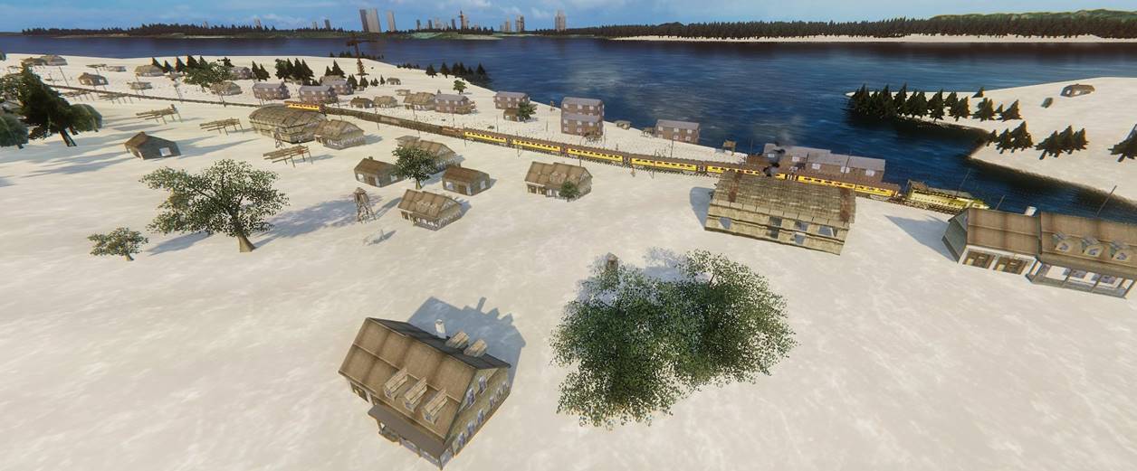
The railtrack autogen, which is controlled by the RailtrackObjects
entity, places objects along rail tracks. First it determines which individual
track is closest to the player and whether it's within range. It then places
objects over a set distance in front, and for the same distance behind. As the
train moves along the track, objects which fall behind will be removed (their
object slots freed) and new objects placed in front. The default setting is 50,
which places objects 25 tracks ahead and 25 tracks behind (a distance of 750
meters each way).
If a map has multiple rail tracks, each one must be controlled by a
separate instance of RailTrackObjects. The Seattle demo map has four.
As with the general autogen, the object parameters are set by a text
data file e.g.GameSDK\Data\Trains\Autogen\Seattle_landclass_A.txt
LAND CLASS
MAX PITCH DISTANCE
SIZE OBJECT HEIGHT
TYPE
ENABLED MIN MAX
DENSITY AMOUNT MIN
MAX OFFSET Z MIN
MAX MIN
MAX
OBJECT FILE PATH
Object Brush,
1, 0,
0, 0.1,
20010, 700,
1000,
0, 1,
1.3, 90, 5000, Objects/Autogen/BuildingB.cgf,
Object Brush,
0, 0,
0,
1,
10, 400,
600,
0, 1,
1.3, 90, 5000,
Objects/Autogen/BuildingC.cgf,
Object Effect,
1, 0, 1,
0.05,
30, 10, 100,
0.2, 0.1, 0.3,
90, 200, smoke_and_fire.ground_fire.big_deck,
Object Brush,
0, 0,
1,
1,
90, 50,
300,
0, 1, 1,
90, 5000,
Objects/architecture/buildings/fishing_houses/fishing_house_a.cgf,
Object Light,
1, 0,
1,
0.7,
90, 5,
150,
3, 0.5,
3, 90,
1000, ,
After the 'Object' keyword, the parameters are:
Type, e.g. Brush, Light, Effect, Group.
ENABLED: values are one if enabled, zero if disabled. If disabled, the
object will not be placed.
LAND CLASS MIN MAX: Allows object types to change along the track. Note:
a full landclass system will be added in a later version.
DENSITY: controls the number of objects placed, values in range zero to
one.
MAX PITCH AMOUNT: sets the maximum terrain pitch and gradient that the
object can be placed on.
The value can contain two separate values: pitch and gradient. The small
values (e.g. 10 or 30) provide the pitch value. If the value is greater than
1000 then it is a compound value that contains both pitch and gradient. In the
example above, the first value is 20010. The small value is 10. The large value
is the integer of 20010 divided by 1000 i.e. 20. Values smaller than 1000 only
contain a small value (pitch).
Pitch: the small value sets the maximum terrain pitch in degrees
(perfectly level terrain has a pitch of zero). If the terrain pitch exceeds the
small value then the object will not be placed.
Gradient: if a large value is present (greater than 1000) then the
terrain height at each corner of the object will be acquired. If any of the 4
heights is more than 7 meters below the object, then the object will not be
placed. The value, after division by 1000, gives the object's default
horizontal size (the maximum displacement in the x and y directions from the
object's centre). The value is multiplied by the random scale factor for this
instance of this object type.
In the above example, the basic value is 20010. After dividing by 1000
and taking the integer, the derived value is 20 meters. The four points that
will be tested for terrain height are offset in the x and y directions by 20
meters multiplied by the scale. If at any of these four points the terrain is
more than 7 meters below the object centre, then the object will not be placed.
As an example, suppose a house is to be placed on the edge of a cliff,
so that half of it is in the air. The pitch parameter will not cull the house
because it is placed on perfectly level ground. However, the gradient parameter
will check the terrain height at each corner of the house, and it will be
culled as required.
DISTANCE MIN MAX: objects will be placed at a random distance from the
tracks, but within these limits.
OFFSET Z: adds a vertical offset, in meters
SIZE MIN/MAX: Sizes are randomly chosen in the min/max range. A value of
one corresponds to the object's default size.
OBJECT HEIGHT MIN/MAX: Objects will be placed only if the terrain height
is within the min/max range. Set the min value slightly larger than the water
height to ensure houses are not placed in the water.
OBJECT FILE PATH: Defines the path to the object e.g. file path and name
of a brush, a group file or effect type.
The rail tracks themselves (and a second set of parallel tracks) are
also placed as autogen objects. If enabled by the Properties settings, the
railtrack autogen will place overhead power cables and will also spawn complete
autogen trains on the second track. Where tracks go below the terrain, the
autogen places a tunnel model. Similarly, where the tracks are above water (or
above the terrain) the autogen places a bridge model.
Three exclusion zones can be defined in the Properties settings (no
autogen objects are placed in an exclusion zone). For each exclusion zone you
set the min and max track numbers, and define whether to exclude on the left or
the right, or both. This is particularly useful when one track branches off
from another, or wherever two tracks run close together. Without exclusion
zones, one track autogen will inevitably place objects right on top of the
other track, and vice versa. As an example, suppose you wish to exclude objects
from track 100 to track 130, and on the right side. In the exclusion Properties
settings, set 100 and 130 for the min and max values, and check the
ExcludeRight box. Note: left and right refers to the directions if you are
looking in the direction of increasing track numbers. The RailtrackObjects
entity will display the local track numbers if you enable the Labels setting.
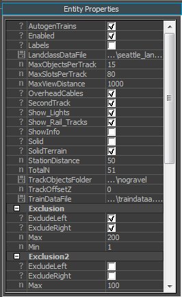
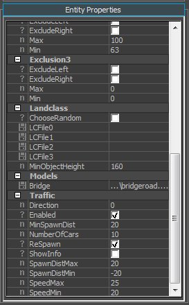
Railtrack Properties Settings
PROPERTIES SETTINGS
AutogenTrains: Enables autogen trains.
Enabled: Overall enable, if not checked no rail tracks or autogen
objects will be displayed.
Labels: If enabled, the track number will be displayed on nearby tracks.
LandclassDataFile: The path to the file that defines the autogen objects
that will be placed along the tracks.
MaxObjectsPerTrack: Defines the maximum number of autogen objects that
will be placed along each 30 meter track section.
MaxSlotsPerTrack: Defines the maximum number of object slots per track
that can be used. Unlike the previous setting, this can be used to limit the
number of objects added by group files or stations.
OverheadCables: Enables the display of overhead cables.
SecondTrack: Enables the display of a second, parallel rail track.
Show_Lights: Enables the display of autogen lights.
Show_Rail_Tracks: Enables the display of the rail tracks.
ShowInfo: Enables the display of debug information.
Solid: If enabled, autogen objects are solid (solid objects may reduce
frame rates by a small amount). Must be enabled for roads.
SolidTerrain: Indicates whether solid terrain is used (terrain created
with brushes).
StationDistance: Average distance between autogen stations (indicated as
a number of 30 meter tracks, so a value of 10 would be a distance of 300
meters). If stations are not appropriate (e.g. for roads) set a large distance
e.g. 9999
TotalN: Sets the total number of rail tracks that will be displayed. For
example, if the value is the default of 51, then 25 tracks will be shown behind
the train and 25 tracks will be shown in front (a view distance of 750 meters).
Larger values will be more realistic, but frame rates will be lower.
TrackObjectsFolder: The path to the folder that contains the track
objects. After entering the path, delete the extra characters incorrectly
appended by Sandbox.
TrackOffsetZ: Sets a vertical offset for the track objects.
TrainDataFile: The path to the file that contains the track data (the
same data file is used by all locomotives/wagons placed on this track).
Exclusion, Exclusion1 and Exclusion2
Exclusions
If two tracks are nearby, their autogen objects will overwrite each other,
so houses and trees may be placed on the tracks. Up to three exclusion zones
can be defined to fix this. In an active exclusion zone autogen objects are not
placed to the right or the left, depending on settings. The settings are:
ExcludeLeft and ExcludeRight: Sets whether objects will be excluded on
the right or left, or both. (Left and right correspond to travel in the
direction of increasing track numbers).
Min and Max: Sets the extent of the exclusion, measured in track
numbers. For example, if Min = 50 and Max = 100, then the exclusion zone covers
all tracks from track 50 to track 100.
Landclass/ChooseRandom: If enabled, at random intervals the landclass file will
be switched randomly to one of the four files in the following list. This gives
more variety (later simulator versions will introduce a full landclass system,
so this is a temporary fix).
LCFile0 to LCFile3: If ChooseRandom is enabled, enter the paths to four
landclass files.
MinObjectHeight: The landclass files define a minimum height for
each autogen object, but this setting provides a global value that overrides
the landclass files. This setting can be used to ensure that objects are not
placed in the sea.
Models/Bridge: Sets the path to the bridge object .cgf file (the bridge
that supports the rail track or road). Rail tracks and roads use a different
bridge model.
ROADS
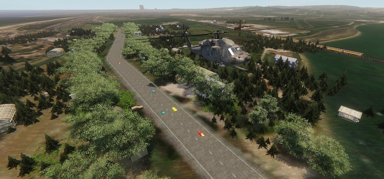
Despite its name, RailtrackObjects can also create roads. Roads are built from
30 meter sections, and they have the same selection of bend angles as the rail
track objects, and also the same names. The Properties setting
TrackObjectsFolder defines where the track objects are located, so if you
choose a folder that contains road models, you will have a road.
For roads, you would normally disable the Properties settings
OverheadCables and SecondTrack. To stop autogen stations appearing, set
StationDistance to a very large value e.g. 9999
Roads can have their own autogen traffic, as set by the Properties
Traffic section:
The Traffic settings are as follows:
Direction: Values can be 0, 1 or 2 0: Traffic flows in
both directions 1: Traffic flows forward only 2: traffic flows
backwards only
Enabled: Enables traffic. If not checked there will be no traffic.
MinSpawnDist: Minimum distance at which a car can be spawned (measured
in road sections).
NumberOfCars: Sets the number of cars that are visible.
Respawn: If enabled, when a car goes beyond the max visibility distance,
it will be deleted and a new vehicle spawned.
ShowInfo: If enabled, the status of each vehicle slot is displayed, used
for debugging.
SpawnDistMax: The maximum distance ahead of the player (the number of 30
meter road sections) where new vehicles will be spawned.
SpawnDistMin: The maximum distance ahead of the player where new
vehicles will be spawned (negative values will spawn vehicles behind the
player).
SpeedMax, SpeedMin: The speed of a spawned vehicle will be randomly
chosen within these limits.
More on spawn distances:
Distances are set as a number of road sections (each section is 30
meters long).
Suppose you are driving along a road and SpawnDistMax and SpawnDistMin
are set to +10 and -10 respectively. When a car is spawned, its relative
position (measured in number of road sections) will be anything in the range
-10 to +10. By chance some cars will be spawned very close to you, e.g. a value
of one. You use the MinSpawnDist setting to stop this happening. Suppose it is
set to 5. If the random value was +1 then it will be forced to +5. Similarly,
if the random value was -1 then it will be forced to -5. Therefore,
irrespective of whether the car is to be spawned ahead of you or behind you,
its spawn distance will be a minimum of 5 road sections (150 meters).
WEATHER
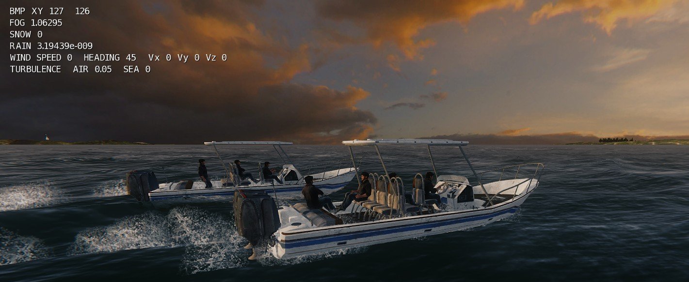
The simulator weather system is controlled by the Weather entity. It
controls the sky dome, clouds, fog, snow, rain, winds and air and sea
turbulence. Each weather variable can be controlled by a monochrome bitmap, so
that the effect varies with x,y position in the map.
Each bitmap should be 8 bit monochrome, size 256 * 256 pixels. The first
four Properties settings define how each bitmap covers the Sandbox map area.

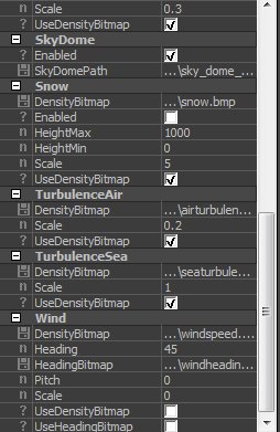
Properties
settings
The Weather Properties settings are shown above. The settings are as follows:
AreaSizeX, AreaSizeY: the x and y size of the bitmap in meters
(clouds have a separate setting). An X size of 10000 would indicate that the
bitmap covers 10 km in the horizontal direction.
CentrePosX, CentrePosY: the location in the Sandbox map that corresponds
to the centre of the bitmap.
The bitmap orientation corresponds to a normal map: up is to the north
and right is to the east. In Sandbox, the y axis points to the north, and the x
axis points to the east. In Sandbox editor mode, if you look directly along the
y axis you are looking north, and the indicated camera heading will be zero.
But note that Sandbox uses the opposite convention to normal: the Sandbox
heading becomes more positive as you rotate the camera to the west (to the left).
All heading values used by the Weather entity are conventional: zero pointing
to the north and becoming more positive as you rotate the camera to the east
(to the right). Values are in degrees.
If the player moves to a location that is "off" the bitmap,
the weather variables will stop updating.
ShowInfo: If enabled, the Weather entity will display information in the top
left of the screen, as shown in the screen shot. BMP X,Y indicates the current
pixel position on the bitmap (conventional bitmap coordinates: X to the right,
Y going down)
Clouds
AreaSizeX, AreaSizeY: the x and y size of the cloud bitmap in meters
(usually larger than for the other bitmaps).
CloudDensityBitmap: the path to the bitmap that defines the cloud
layout.
CloudXMLFile: the path to the XML file that defines the cloud.
Enabled: sets whether clouds will be displayed or not.
HeightMax, HeightMin: cloud heights are randomly set, but within these
two limits.
NClouds: the number of clouds that will be displayed.
SizeMax, SizeMin: cloud sizes are randomly set, but within these two
limits.
Vx, Vy: cloud movement speeds in meters/sec.
Fog
Density: sets the overall amount of fog.
DensityBitmap: path to the bitmap that controls the variation of fog
across the Sandbox map.
Enabled: sets whether fog will be displayed or not.
UseDensityBitmap: sets whether the density bitmap will be used. If not
used, fog density will be constant and set by the Density value.
The fog density is also controlled by a TOD setting, so the
amount of fog may be different at different TOD settings.
Rain
DensityBitmap: sets the path to the density bitmap.
Enabled: sets whether rain will be
displayed or not.
HeightMax, HeightMin: rain will be displayed only
between these height limits.
Scale: sets the overall amount of rain.
UseDensityBitmap: sets whether the density bitmap
will be used. If not used, rain density will be constant and set by the Scale
value.
SkyDome
Enabled: sets whether the skydome will be displayed
or not.
SkyDomePath: sets the path to the material file, usually located in
Objects/Clouds/SkyDomes. This sets the skydome material that will be used when
the game starts.
When in-game, the skydome can be changed with ESKY command. For example,
the command ESKYD will select skydome D (sky_dome_D.mtl). If the ESKY command
has been used, subsequent saved games will store the value, so that when the
game is reloaded it will have the same sky. Saved game files can also be edited
to change the skydome e.g. SKYDOME objects/clouds/skydomes/sky_dome_d.mtl,
Snow
DensityBitmap: sets the path to the density bitmap.
Enabled: sets whether snow will be
displayed or not.
HeightMax, HeightMin: snow will be displayed only
between these height limits.
Scale: sets the overall amount of snow.
UseDensityBitmap: sets whether the density bitmap
will be used. If not used, snow density will be constant and set by the Scale
value.
TurbulenceAir
DensityBitmap: sets the path to the density bitmap.
Scale: sets the overall amount of air turbulence.
UseDensityBitmap: sets whether the density bitmap
will be used. If not used, air turbulence density will be constant and set by
the Scale value.
TurbulenceSea
DensityBitmap: sets the path to the density bitmap.
Scale: sets the overall amount of sea turbulence.
UseDensityBitmap: sets whether the density bitmap
will be used. If not used, sea turbulence density will be constant and set by
the Scale value.
Sea turbulence sets how much ships will pitch and roll.
Wind
DensityBitmap: sets the path to the density bitmap.
Heading: sets the wind heading (direction) if a heading bitmap is not
used. A heading of 90 degrees means that the wind is blowing from the west.
HeadingBitmap: path to the bitmap that sets the wind heading at the
player location. The heading in degrees is equal to the bitmap pixel value
multiplied by 2, so if the pixel index is 50 the wind heading will be 100
degrees.
Pitch: sets the pitch of the wind in degrees (the vertical wind
component).
Scale: sets the overall amount of wind speed.
UseDensityBitmap: sets whether the
density bitmap will be used. If not used, wind speed will be constant and set
by the Scale value.
UseHeadingBitmap: sets whether the density bitmap will be used. If not
used, wind heading will be constant and set by the Heading value.
S
I M U L A T O R E D I T O R
The simulator editor can be used to create and edit waypoints, rail
tracks, vehicle lights, terrain lights and autogen objects.
PLACING THE EDITOR IN A MAP
1. In Sandbox, open the Entity rollup, open the Aircraft category, and
drag the EditorA entity onto the map.
2. Move the editor to the point where you want the waypoints or rail track
to start. Do not rotate the entity (the angles must be 0,0,0).
3. On the Entity rollup, click Flow Graph -> Create and load the
supplied flow graph objects\aircraft\AircraftFiles\ EditorFlowGraph.xml
Any number of editor instances can be loaded into a map, but only one
should be enabled.
EDITOR SETUP
The editor is configured by its Properties settings. Click the editor to
select and look at the Entity rollup at the right. You will see 14 settings.
1. The first 4 specify which type of object will be edited.
Currently waypoints, rail tracks, autogen objects and vehicle lights are
supported. Check Edit_Waypoints, Edit_Rail_Tracks, Edit_Objects or
Edit_VehicleLights and ensure the other three are unchecked.
2. EditorEnabled. If checked, the waypoints or rail tracks will be displayed,
and when you press CTRL-G you will enter editor mode. Check the box to enable.
3. ShowEditorText. If disabled, the editor will not display any text. If no Edit_
boxes are checked and ShowEditorText is also disabled, you can use the editor
to slew around the map and observe the action in-game.
4. LoadTrackFile / LoadWaypointFile. These select the paths for the track and
waypoint data files. The files are loaded automatically.
5. SaveTrackFile / SaveWaypointFile. These select the paths where data will be
saved (press F9 to save data).
6. SaveTrainFile. This selects the path for the train data file. This file will
be loaded by any locomotives or wagons that use the rail track. You can select
an existing file and then edit the path as required to e.g. TrainData.txt. The
train data file is saved when you press F9.
7. TrackObjectsFile. After creating and editing the rail track you can save the
tracks as a group file (press key F8). After disabling the editor you can load
the group file. The track is now composed of standard brushes. This is the
preferred method, as frame rates will be higher, particularly for large tracks.
Enter a path for the group file that will be created. To save the group file
when the editor is running, press F8.
8. Model. You can select any model for the editor, or if you enter a blank, no
model will be shown. The editor entity is indicated by a small circular icon.
9. SolidTerrain. If you are using 'solid' terrain (terrain created in a
modelling program and exported as brushes) then check the box. If you are using
standard terrain, then uncheck the box.
10. ShowWaypoints. If checked, waypoints will be shown (as red spheres with a
number), otherwise the waypoints will not be shown. If you are editing rail
tracks, ensure that ShowWaypoints is disabled.
11. Objects.BitmapFilePath. This defines the path to the bitmap file (type
.bmp, 8 bit colour) that controls the positions of the autogen objects.
12. RecordWaypoints. If enabled, you can save waypoints to file as you fly an
aircraft.
USING THE EDITOR
If the editor is enabled by its Properties setting, it will run
continuously in game mode. You will see editor text on the left half of the
screen. All the editor commands are listed. If you want to run the game in
normal mode (e.g. to test it) you can disable the editor by its Properties
setting.
You can pan your view around by moving the mouse. Press the mouse LH and
RH buttons to move forwards and backwards. You can also use the four arrow keys
to move forwards/backwards/sideways. Press PageUp or PageDown to adjust your
height. To adjust the speed of movement, roll the mouse button (forwards for increased
speed). These functions allow you to move around the map to find an area of
interest very easily.
EDITING WAYPOINTS
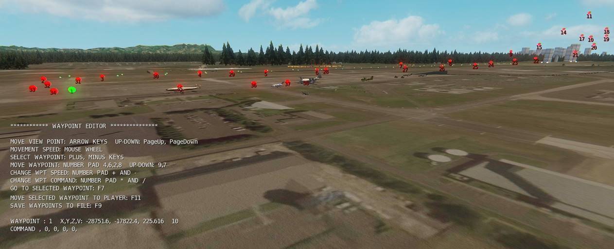
WAYPOINT EDITOR INTERFACE
To set waypoint mode, enable (check) the Properties Edit_Waypoints
setting.
Waypoints allow vehicles to follow complex paths in three dimensions.
Individual vehicles are set up to follow waypoints by means of their Properties
settings. By editing the waypoint file, vehicles can be programmed to execute
complex commands, from emitting coloured smoke to dropping cargo on parachutes.
When you start game mode you will see each waypoint as a red sphere with
a number, as shown above. Press the plus and minus keys to change the selected
waypoint. The selected waypoint is coloured green.
To move a selected waypoint, press the number pad arrow keys. The
waypoint will move in the corresponding direction. The movement speed is
controlled by the player movement setting (roll the mouse wheel).
You could create new waypoints as follows:
1. Press the minus key until waypoint 1 is selected.
2. Move your viewpoint to the first waypoint position.
3. Press F11. This moves the first waypoint to your position and also
increments the waypoint number.
3. Move to the second waypoint position and press F11 again.
4. Move to all the other waypoint positions in turn and press F11 at each one.
Finally, press F9 to save the waypoints to file. If you exit game mode without
saving, your edits will be lost. Note: the paths for the loaded and saved
files must be correctly set in the editor's Properties settings.
To move your viewpoint to a selected waypoint, press F7.
To insert a new waypoint, press key Insert. A new waypoint will be inserted
after the selected waypoint, and all subsequent waypoints shifted forwards. If
waypoint 10 is currently selected, then the new waypoint will be no. 11. The
original waypoint 11 will now be waypoint 12, and so on.
WAYPOINT PROPERTIES SETTINGS
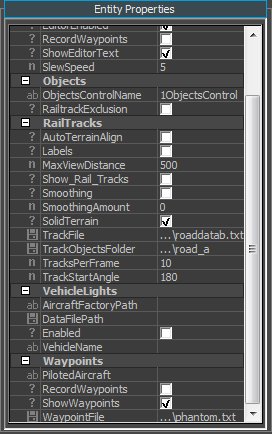
PilotedAircraft:
RecordWaypoints:
ShowWaypoints: Display each waypoint as a small sphere and waypoint
number.
WAYPOINT COMMANDS
Various commands can be executed when the vehicle reaches a specified
waypoint. The waypoint command and its parameters are displayed on the second
line up.
To toggle through a selection of available waypoint commands, press keys
number pad * and /. Additional commands can be added by editing the waypoint
file. Refer to the waypoints section of this manual for information on
waypoints and a full list of waypoint commands.
EDITING
RAIL TRACKS
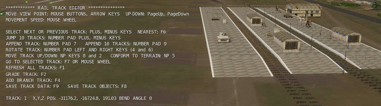
RAIL TRACK EDITOR INTERFACE
To set rail track mode, enable (check) the Properties
Edit_Rail_Tracks setting.
You can place and edit hundreds of rail tracks, using the standard
Crysis track models. When correctly set up, locomotives and wagons will
accurately follow the tracks. You edit the tracks by changing the bend angle of
the selected rail track or by appending new tracks to the end of the track.
When you select a rail track and change the bend angle, all following tracks
are automatically updated.
The selected track number, position and bend angle are displayed at the
bottom of the editor text. Press the plus and minus keys to select a track. You
can also use the number pad plus and minus keys to change the selection by
larger amounts (useful if you have hundreds or thousands of tracks). The
selected track is marked by a green label with the track number.
To change the bend angle of the selected track, press the number pad
left and right arrow keys. If you are looking in the direction of increasing
track number (forwards) then the right arrow key will rotate the following
tracks to the right. The bend angle is indicated at the bottom of the editor
text.
The track angles can be changed only in large steps (the available track
bend angles). Finer angle control may be needed e.g. to accurately match the
join between a branch and main track. The selected track can be precisely
rotated by small amounts (tweaked) by pressing number pad keys 1 or 3 (the keys
directly below the arrow keys). To adjust the angle step changes, roll the
mouse wheel. By selecting a small gain, the track angle can be adjusted in
small steps e.g. one hundredth of a degree.
You can move the selected track up or down with number pad keys 8 and 2
(8 for up).
More usefully, you can make every track conform to the terrain by
pressing number pad 5.
You can add additional tracks to the end of the track (append). Number
pad 7 adds a single track, while number pad 9 adds ten tracks.
You can move your viewpoint to the selected track by pressing F7.
Finally, you can save your edited track by pressing F9. The track data
file will also be used by all locomotive or wagon entities placed on the track.
To save the track data as a group file, press F8. The tracks can then be
loaded as standard brushes by loading the group file. This should always be
done for the final map, as performance will be better. In fact, once you've
finished creating your tracks and you've exported as a group file, you can then
delete the editor from the map. You can always reload the editor if you need to
do further editing.
Note: if you use the railtrack autogen you don't need the group file, as
the autogen will use the train data file to place the tracks, and a second set
of parallel tracks.
After saving the track data, select a locomotive (or wagon) that you
previously loaded into the map. Near the bottom of the locomotive's Properties
list you will see the train settings. Open PathDataFile and select the track
data file, as specified in the Editor Properties. When you click Reload Script
you should see the locomotive 'jump' onto the track, with its wheels correctly
positioned. You can set the actual position on the track by adjusting the
StartDistance setting.
PROPERTIES
SETTINGS
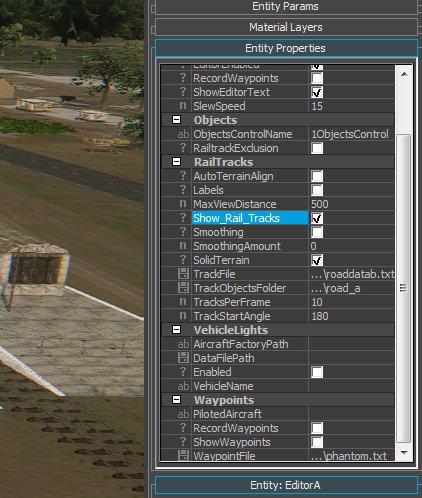
AutoTerrainAlign: When new tracks are appended, they are automatically
aligned to terrain
Labels: Each track has a label giving the track number.
MaxViewDistance: Maximum distance at which tracks are displayed.
Smoothing:
SmoothingAmount:
TrackFile: The path to the file that contains the track data.
TrackObjectsFolder: The path to the folder that contains the track
object files.
NOTE: Sandbox has a bizarre bug/feature. If you navigate to a folder, as
opposed to a file, Sandbox will incorrectly append the folder name to the path,
so it will be wrong. After choosing the path, carefully delete the incorrect
characters that Sandbox appended.
TracksPerFrame: When the editor is updating the tracks (e.g. after
changing a track bend angle) this setting determines how many tracks will be
updated in each frame.
TrackStartAngle: The angle (heading) of the first track.
ADDING BRANCH TRACKS
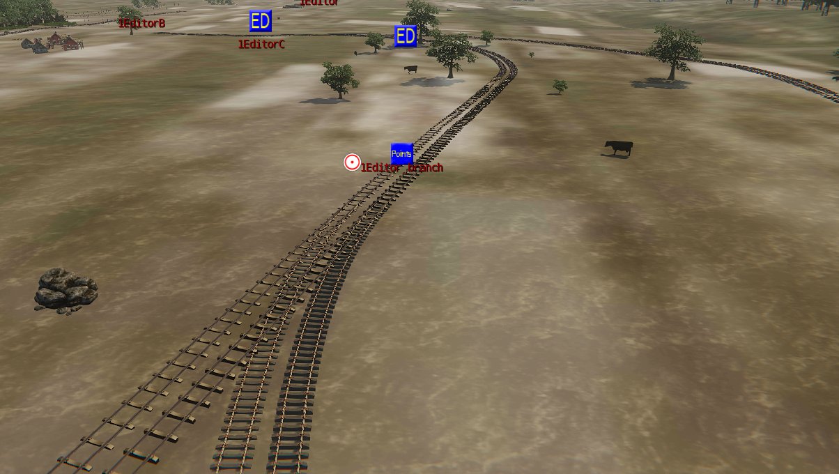
Branch tracks can be added manually, but the editor includes
a tool that creates branch lines automatically. To activate the tool, press F4.
Procedure:
1. Check that this path and file exist:
GameSDK\Data\Trains\TrackData\BranchTrack\BranchEntitiesFormat.grp
If necessary, create the directories and place the file inside
BranchTrack.
2. Run the railtrack editor with the main track selected (the new branch track
will be attached to the main track).
3. Press the plus and minus keys to select the track that the branch track will
be attached to. Preferably it should be a straight track, but curved tracks
should also work.
4. Press F4 to create the branch track. A group file and a track data file will
be saved. A screen message confirms that a group file has been saved.
5. Exit the editor. From the Sandbox Modify top menu, select Load Objects and
select the group file
GameSDK\Data\Trains\TrackData\BranchTrack\BranchEntities.grp
When you click Open three entities will be loaded close to the selected
track: a new editor, RailtrackObjects and Points. Their Properties have
automatically been set up for the new branch line.
6. Disable the previous editor and enable the new one (named 1Editor_branch).
When you click Reload Script you should see the new branch line. The track data
is copied from the main line.
7. Run the editor and edit the branch track as required. When finished editing,
press F9 to save. Note: even if the track has not been edited, it must be saved
from the editor before the track file can be used by RailtrackObjects.
8. Enable the new RailtrackObjects entity and click Reload Script. The double
track and railtrack autogen will appear.
9. Disable the new editor so that it does not display the track.
10. Set up the RailtrackObjects Properties as required e.g. to disable the
double tracks.
11. Move the track file BranchTrack.txt to a suitable location and give it a
suitable name. Update the Properties settings in the three entities to reflect
this change. Note: if BranchTrack.txt is not removed/renamed, it will be
over-written the next time the branch track tool is used.
ROADS
The editor can also create and edit roads. Roads are built from 30 meter
sections, and they have the same selection of bend angles as the rail track
objects, and also the same names. The Properties setting TrackObjectsFolder
defines where the track objects are located, so if you choose a folder that
contains road models, you will have a road.
RAIL TRACK TUTORIAL
This tutorial describes the process of creating and editing rail tracks,
and placing a train that will follow the tracks.
1. From the entity rollup, open the Aircraft group and drag the Editor onto the
terrain. The Editor position sets the start position of the track.
2. ****
3. Select the Editor and load the flow graph objects\aircraft\AircraftFiles\
EditorFlowGraph.xml
4. In the Editor Properties, enable (check) these settings:Edit_Rail_Tracks,
EditorEnabled. Ensure all other options are disabled (SolidTerrain must be
disabled if you're using standard terrain).
5. Click Reload Script.
You should now see the track. If not, check that LoadTrackFile is set to
scripts/entities/trains/data/track_data.txt and that the file is present. If
correct and track does not appear, check that the editor is correctly
installed.
6. Enter CTRL-G to start game mode. You should see Editor text on the left of
the screen. Move the mouse to pan your view. Press the LH mouse button to move
forward (RH mouse button to move back). Roll the mouse button to adjust your
move speed.
You should now be able to easily move around the map e.g. to follow the
track.
7. To make the tracks conform to the terrain, press number pad 5.
8. Move to the start of the track. Press the plus key several times. The
indicated track number increases. The selected track is marked by a green
label.
You edit the track by selecting it and changing its bend angle. After
editing, the track may no longer conform to the terrain. To correct this, press
number pad 5.
9. Use the plus and minus keys to select track 5. Press number pad keys 4 and 6
to change the bend angle of the selected track. When the angle is changed all
the following tracks are immediately updated. By selecting the tracks in turn
and adjusting their angles you can edit the entire track.
10. When you have finished editing, press function key F9 to save to the track
file. Note: the SaveTrackFile Properties setting must call up a valid
directory. The default setting will be the same as LoadTrackFile. You should
check that track data is being saved correctly before doing any significant
editing. If data is saved correctly any changes to the track that were saved
will appear the next time you start game mode or click Reload Script.
If the Load and Save Properties are the same, the next time you start
the Editor it will have the same track data that you saved.
When you have edited the tracks, you can save as a group file and then
load as standard brushes. To do this, enter a suitable path into
TrackObjectsFile. When running the editor, press F8 to save the group file.
The next task is to create a train that will run on the tracks. Train
entities use a train data file to enable them to follow the track. The editor
saves a file defined by the SaveTrainFile Properties setting. The file is saved
each time you press F9. Ensure the setting is valid. The default settings
should be appropriate, but you can of course change the settings as required.
For correct operation of the train, the Editor SaveTrainFile and the locomotive
PathDataFile settings must be identical.
11. From the entity rollup, open the Trains category and drag the
LocomotiveTest entity onto the terrain near the beginning of the track.
12. Load the flowgraph objects\aircraft\AircraftFiles\ EditorFlowGraph.xml
13. Set the Model (in Properties, top section) to
objects/library/vehicles/Diesel_train_engine/Diesel_train_engine.cgf
14. The entity's Properties (in the Trains category) should be set up as
follows:
ContactPointFrontY 5.79
ContactPointRearY -10.24
Height 0.3
ModelZRotation -90
PathDataFile scripts/entities/trains/data/train_data.txt
RearY -10.24
StartDistance 20
After entering these settings, click Reload Script. You should now see
the Locomotive correctly placed on the track. If you drag the StartDistance
setting it will move along the track.
You can now drive the Locomotive, using normal controls (type in eall to
start engines, press plus and minus keys to control thrust, F2 to pan your
view, F6 for external view, F3 for walk mode etc).
15. To add a flat wagon, make a copy of the locomotive and enter these
values:
Set the Model (in Properties, top section) to
objects/library/vehicles/rail_trailer/container_trailer.cgf
ContactPointFrontY 7.5
ContactPointRearY -7.6
Height 0.94
ModelZRotation 0
PathDataFile scripts/entities/trains/data/train_data.txt
RearY -10.24
StartDistance 30
Adjust the StartDistance to set the wagon's position. If you make
additional copies of the wagon to build a train you will need to adjust only
the StartDistance setting.
If you place the wagons immediately behind the locomotive they will be
automatically coupled to form a train. If you place the wagons some distance in
front and then drive the locomotive forwards, the wagons will be automatically
coupled to form a train. The same applies if the wagons are placed some distance
behind and you drive the locomotive backwards.
Many aircraft functions (e.g. walk mode) also work for trains where
applicable (e.g. view modes). Refer to the aircraft manual for more details.
Note that the editor can be used to create waypoints for trains, for example to
have them run a route, stop for a period of time at a station and then
continue.
EDITING AUTOGEN OBJECTS
Autogen is a major enhancement for the flight simulator system. It
allows the display of possibly millions of objects on the terrain (e.g.
buildings and trees) while maintaining high frame rates. As you fly along or
look around, autogen objects are dynamically hidden, unhidden and moved as
required. When objects fall sufficiently far behind you they can then be
re-used by placing them in front of you or to the side. In effect the
objects are being constantly re-used as you fly along. This is why frame rates
are high: to get a similar object density with a large conventional map,
hundreds of thousands or millions of objects would have to be placed in the
map.
Autogen is implemented with two Lua entity types: ObjectsControl and
ObjectsSpawner. ObjectsControl controls the high level aspects of the system,
for example determining when a group of objects should be hidden, un-hidden or
moved. Normaly only one instance of ObjectsControl would be placed in a map.
The ObjectsSpawner entity controls the individual objects. They are not
placed in the map. 25 ObjectsSpawner entities will be spawned in-game by
ObjectsControl. Each ObjectsSpawner entity places objects, usually in a 5
kilometer square centered on the entity's location. The objects are placed in
the entity's slots.The height of each object has to be individually set so that
it correctly sits on the terrain.
The collection of available object types is defined by a script file.
The entity loads data from a bitmap file (type .bmp, 8 bit colour, size up to
1024*1024 pixels) which defines which object type should be placed at any location.
Currently the object types supported are brushes, effects and group files (a
pre-assembled group of brushes).
The autogen layout in the map can be set by editing the bitmap file in a
paint program. For more accurate layouts, the editor can directly paint autogen
objects onto the terrain, and the edited version can be saved back to the
bitmap file.
Before editing objects, you should enable these editor Properties
settings: Edit_Objects, EditorEnabled and ShowEditorText. All other check boxes
should be disabled. Click on Objects.BitmapFilePath and navigate to the bitmap
file e.g. GameSDK/Data/Autogen/Objects_Seattle.bmp
Enter CTRL-G to start game mode. You will see the editor text on the LH
of the screen. The top lines of text show the available key commands, e.g.
"SAVE TO BITMAP FILE: F9"
The object index indicates the selected object. For example if the index
is 5 then the fifth object in the objects script is selected. The complete path
for the object is also shown. If object painting is enabled the selected object
will be shown on the terrain where the object or objects will be painted.
There are three object painting modes: OFF, PAINT SINGLE OBJECT and
PAINT MULTI OBJECTS. Press the SPACE bar to cycle through the modes. If PAINT
MULTI OBJECTS is selected, two additional lines appear: BRUSH SIZE and PAINT.
BRUSH SIZE indicates the size of a square (in meters) in which objects will be
painted. PAINT indicates the number of objects that will be painted.
To paint an object or objects, press the LH mouse button. You will
immediately see the additional objects on the terrain, but note that they will
appear differently (e.g. different sizes) in normal game mode.
In paint mode the LH mouse button is used for painting, so you can't use
it to slew forwards. However, you can use the four arrow keys to slew in any
direction.
When you've finished painting objects, press F9 to save to the bitmap.
All autogen objects will be deleted and re-generated, thus showing the final
effect that will be seen in-game. You will normally see your new objects
displayed according to the new bitmap data and the objects script file. You can
delete and re-generate (i.e. refresh) the objects at any time by pressing key
X. If your new objects do not appear, move back a small distance and refresh
(key X). Note that the objects script defines a minimum and maximum
altitude, so if the terrain is not in the specified range the objects will not
appear.
EDITING VEHICLE LIGHTS
To set vehicle lights mode, enable (check) the Properties
Edit_VehicleLights setting.
Any number of lights can be added to a vehicle. A number of
parameters for each light can be set e.g. enable shadows, illumination radius,
brightness.
After editing, the editor saves light data to a text data file. Here is
an example:
Label Command
Pos
Angles Radius Brightness R
G B Shadows FOV On
Light 1, Headlight1, el1, 0, 22.7996,
5.01137, 5, 6, 20, 9.91942,
7.22, 1, 1, 1, 0, 0, 1,
Light 2, Headlight2, el1, 0, 30.5674,
5.01137, 5, 6, 20, 12.2023,
7.22, 1, 1, 1, 0, 0, 1,
Light 3, Headlight3, el1, 0, 39.3014,
5.01137, 5, 6, 20, 14.5151,
7.22, 1, 1, 1, 0, 0, 1,
Light 4, Headlight4, el1, 0, 49.6244,
5.01137, 5, 6, 20, 15.7321,
7.22, 1, 1, 1, 0, 0, 1,
Light 5, Headlight5, el1, 0, 65.6857,
5.01137, 5, 6, 20, 20.7205,
7.22, 1, 1, 1, 0, 0, 1,
Light 6, Headlight6, el1, 0, 87.4916,
5.01137, 5, 6, 20, 26.4135,
7.22, 1, 1, 1, 0, 0, 1,
Light 7, Cockpit1, el2, -0.5948, 6.301,
3.337, 4, 5, 6, 1.10407, 0.208075, 2,
0.7, 0.7, 0, 0, 1,
Light 8, Cockpit2, el2, 0.580114, 6.41088, 3.33787 4,
5, 6, 1.10407, 0.208075, 2, 0.7, 0.7,
0, 0, 1,
Light 9, Cockpit3, el2, 0.490496, 7.07241, 3.14154 4,
5, 6, 1.10407, 0.208075, 2, 0.7, 0.7,
0, 0, 1,
Many of these values can be adjusted in the editor, and you will
instantly see the effect of these changes. The values are:
Label: a descriptive name.
Command: the keyboard command that will toggle the light on and off.
Pos: the x,y,z position of the light in vehicle local coordinates.
Angles: x,y,z rotation angles that define the orientation of the light
(for directed light beams).
Radius: the radius of the light sphere, in meters.
Brightness: the light's brightness.
R G B: the RGB brightness values, used for setting the colour.
Shadows: enables or disables shadows (values one to enable, zero to
disable).
FOV: sets the field of view for directed light beams.
On: determines whether the light is on or off when the game is started
(used only be the editor, normall vehicles will always start with all lights
off).
After editing the vehicles, press F9 to save the file. This file is used
by the editor only. When F9 is pressed the editor saves a second file. An
example:
{Label="Headlight6", Command="el1", Pos={x=0,
y=87.4916, z=5.01137}, Angles={x=5, y=6, z=20}, Radius= 26.4135,
Brightness= 7.22, R= 1, G= 1, B= 1, Shadows= 0,
FOV= 0, On=0, SlotN=&,
{Label="Cockpit1", Command="el2", Pos={x=-0.594813,
y=6.30101, z=3.33787}, Angles={x=4, y=5, z=6}, Radius=
1.10407, Brightness= 0.208075, R= 2, G= 0.7, B=
0.7, Shadows= 0, FOV= 0, On=0, SlotN=&,
{Label="Cockpit2", Command="el2", Pos={x=0.580114,
y=6.41088, z=3.33787}, Angles={x=4, y=5, z=6}, Radius=
1.10407, Brightness= 0.208075, R= 2, G= 0.7, B=
0.7, Shadows= 0, FOV= 0, On=0, SlotN=&,
{Label="Cockpit3", Command="el2", Pos={x=0.490496,
y=7.07241, z=3.14154}, Angles={x=4, y=5, z=6}, Radius=
1.10407, Brightness= 0.208075, R= 2, G= 0.7, B=
0.7, Shadows= 0, FOV= 0, On=0, SlotN=&,
{Label="Cockpit4", Command="el2", Pos={x=-0.667464,
y=6.7152, z=3.10289}, Angles={x=4, y=5, z=6}, Radius=
1.10407, Brightness= 0.208075, R= 2, G= 0.7, B=
0.7, Shadows= 0, FOV= 0, On=0, SlotN=&,
{Label="Cabin1", Command="el3", Pos={x=-0.00917355,
y=4.87328, z=3.22805}, Angles={x=4, y=5, z=6}, Radius=
2.71258, Brightness= 1, R= 1, G= 1, B= 0.7,
Shadows= 0, FOV= 0, On=0, SlotN=&,
{Label="Cabin2", Command="el3", Pos={x=0.106165, y=3.78604,
z=3.22201}, Angles={x=4, y=5, z=6}, Radius= 2.71258,
Brightness= 1, R= 1, G= 1, B= 0.7, Shadows= 0,
FOV= 0, On=0, SlotN=&,
This file contains the same basic information, but it has been formatted
into Lua code. When you've finished editing the lights and saved the files, you
then use Aircraft Factory to create the final vehicle code that uses the
lights. To do this, you need to enable the lights script function in Aircraft
Factory and also enter the path to the Lua-format data file. Alternatively, you
can paste the above code straight into the existing Lua file, providing it has
already been set up to use lights.
The Properties settings for vehicle lights (inside the editor Properties
VehicleLights category) are as follows:
AircraftFactoryPath: the path to the AF directory where the Lua-format
file is to be placed. This file is used by AF when it creates the vehicle code.
DataFilePath: the path where the data file is to be placed (this is the
file used by the editor).
Enabled: sets whether the lights will be visible when editing. Must be
enabled when editing the lights.
VehicleName: this defines which vehicle is to be used when lights are
placed during editing.
When using the editor in-game, its text display lists all available
commands.
To adjust the radius, brightness or colour:
1. Press a key to choose the function e.g. S for radius or T
to adjust the R colour component.
2. Press the plus or minus keys to adjust the value. The
values are shown in the text display, and you will instantly see the change in
the lighting.
3. To change the adjustment speed, press the number pad * or
/ (multiply or divide) keys. This setting controls the light movement functions
also (number pad arrow keys, 7 and 9).
To change the selected light, press F6 and F7. The lower part of the
text display shows the selected light number, its label and the main parameters.
Press O (the letter O) to toggle the selected light on or off.
When editing the lights, each light that is on is indicated by a red
sphere. The lights and spheres are actually placed in the target vehicle
entity. To remove the lights and spheres after editing, disable the editor, and
also disable VehicleLights enabled, and click Reload Script. Then select the
target vehicle and click Reload Script.
You can create new commands to control the lights, but the command must
begin with the letter 'E' to ensure it does not clash witjh existing commands.
I use a standard set of commands, EL1 to EL4 (in lower case), going from the
front to the rear, as follows:
EL1: taxi or headlights.
EL2: cockpit lights
EL3: cabin lights
EL4: tail lights, and all other external lights
You can also control the lights with the 'L' command.
THE
WALKER ENTITY
Walker is a Lua animated vehicle entity, the main difference being
that instead of running on wheels or tracks, it runs on legs. It is a
human/animal character with a human/animal model and animations. The model is
set by Properties/Model. To set a character, browse to Objects/Characters....
and after choosing the character click Reload Script.
Like any other vehicle Walker can be entered by the player with
the F command. It uses the standard walk mode commands:
Pan the view: move the mouse
Walk forwards: LH mouse button
Walk backwards: RH mouse button
Adjust walk speed: press the middle mouse button
Adjust walk height: roll the mouse wheel
To make Walker the default player mode, enable the Aircraft Control
Properties UseWalker setting. If enabled, when you press CTRL-G for game mode,
you will be immediately placed in Walker. When walking around the map in
Walker, simulator vehicles can be entered as normal by the F command. When the
vehicle is exited (the O for Out command) the player will be automatically
placed in Walker.
Like any other simulator vehicle, Walker can operate in AI mode e.g.
following waypoints or attacking targets.
The default idle and walk animations are set in
Walker Properties (Idle and Walking in the Anim section).
When following waypoints, Walker can change its animations by using the
SetAnimation waypoint command.
Walker can select and fire weapons in the same way as
the B-25 and Heinkel: press Right Shift to enable weapons and select weapons by
pressing the middle and RH mouse buttons, press LH mouse button to fire the
weapon.
���������� W O R
L D�� S Y S T E M
�� 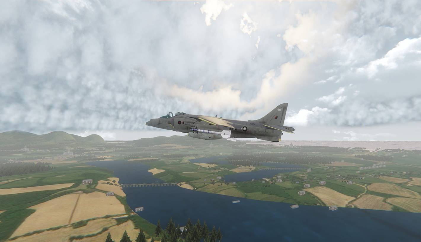
�
� The world system creates scenery that covers
the entire world, allowing flights and journeys over thousands of miles. The
terrain is built from 14km * 7km terrain grids. The terrain and textures for
each grid type is controlled by landclass data.
� As an example, suppose the landclass value
for a grid is 50. The terrain type is then �green fields�. Green fields has 6
variations. To give more variety, when the code loads a green fields grid it
will randomly choose one of the 6 variations. In the screen shot below, the
Harvard is flying over a �town� grid (landclass = 80).
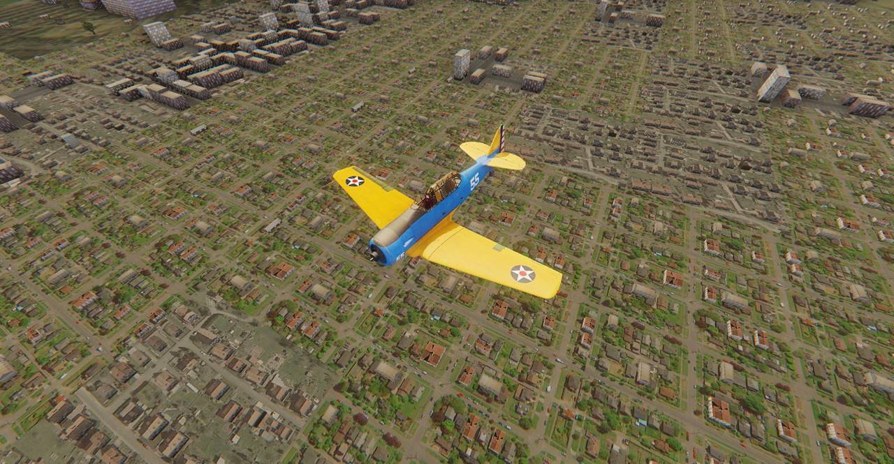
�
� As the player moves across the world, all
game elements (e.g. the player, terrain grids, buildings and trees) are
regularly moved back so that the player is never more than around 5 km from the
Sandbox origin. �Because the jumps every 5km move all the
visible game elements by the same amount, the relative movements are zero and
the jumps are essentially invisible to the player. Even after travelling
thousands of miles, the player will always be just a few kilometres from the
origin. This unique method allows the entire world to be packed into Sandbox.
�The landclass data for the world is stored as
a .bmp image file (shown below). The world is covered by 2784 * 2784� 14 * 7 km grids. Each pixel of the bitmap
represents the landclass value for one terrain grid, so the bitmap resolution
is also 2784 * 2784. The bitmap is 8 bit colour, allowing up to 256 landclass
types. Where possible the colour represents the landclass type, so �green fields�
is green.
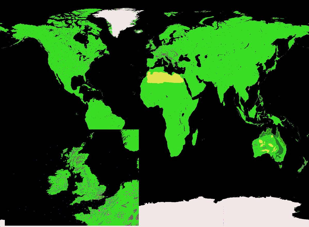
� Where terrain grids meet the ocean (e.g.
beaches), the code automatically adds coastline grids as shown below.
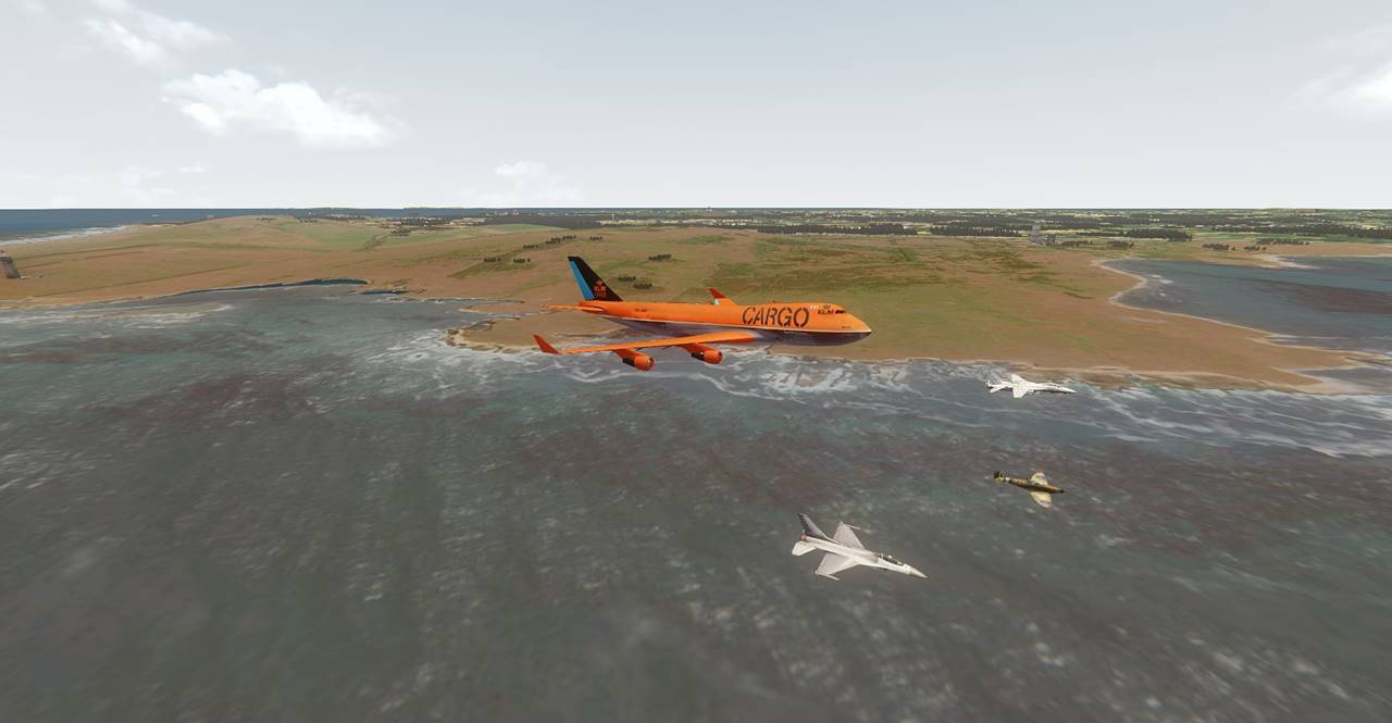
� The available landclass types are given
below:
� 0 (zero):�������� Water
� 1 to 9:������������ Water with ships following
waypoints and executing commands
� 20:���������
Desert
� 30:���������
Plain
�40:����������
Forest
�50:��� ������Green fields (6 variations).
51:���������� Green fields with hills (3
variations).
60:���������� Mountains
70:���������� Snow (4 variations).
80,
81, 82:� Town (3 types).
90,
91, 92: City (3 types).
100:������� Heathrow Airport
102:������� Shoreham Airport
103:������� Manston Airport
104:������� Goodwood Airfield
� Large numbers of assets (both static and
animated) can be placed on the terrain grids. The asset types currently
supported are as follows:
1.
Area autogen. Static objects (brushes)
and effects can be placed over the area of the grid. The layout is defined by
an 8 bit bitmap; each pixel defines an object type. The code places each object
on the terrain surface by sensing the terrain height at that point. This method
allows large numbers of objects to be easily placed simply by painting on the
bitmap.
2.
�Group file objects. Static objects, effects
and entities (e.g. vehicles or level crossings) can be loaded from a group
file. Although more setting up is required, the benefit of this method is that
objects can be placed precisely so that buildings and trees etc can be placed
on corresponding images of the terrain texture.
3.
Rail tracks. A rail track will be
placed if the grid has a standard rail track file. Random AI trains will be
placed on the rail track.
4.
Roads. A road will be placed if the
grid has a standard road file. AI traffic will be placed on the road.
5.
Linear autogen. If the grid has a
standard track autogen data file, autogen objects will be placed along the rail
tracks and roads.
6.
AI vehicles. If the grid has a
standard game file, the vehicles specified by the file will be spawned and
their Properties set. For example, the Heathrow grid (landclass = 100) will
have a number of aircraft that repeatedly taxi, take off, fly some circuits and
land again.
7.
Ground lights. If the grid has a
Lights file, lights will be placed on the terrain according to the data in the
file e.g. town or runway lights.
� The world system is implemented with three
Lua entity types: TerrainControl, TerrainSpawner and GridObjectsSpawner.
TerrainControl spawns and controls instances of TerrainSpawner and
GridObjectsSpawner (typically 200 of each in a 10 * 20 grid). As the player
drives or flies across the world, two kinds of event can occur, as follows:
� 1. The player x or y Sandbox coordinate
exceeds 5000 (5 km). When this occurs, TerrainControl will move all map
elements (e.g. terrain, autogen objects, player vehicle and AI vehicle
entities) back 5km, thus ensuring that the player is never more than around 5
km from the Sandbox origin. Because everything in the map is moved by the same
amount, in most cases the player will not notice the jump. The terrain and
object entities are all children of a parent entity, so only the parent entity
has to be moved. This method allows the player to make journeys of unlimited
length around the world. The terrain and autogen objects will change according
to the local landclass values. One large benefit of this method is that cockpit
vibration is eliminated, as the player is always close to the Sandbox origin.
� 2. One or more terrain grids behind the
player have fallen so far behind as to exceed the maximum distance (set by
TerrainControl Properties). When this occurs TerrainControl will move the
terrain entity forward so it is now in front of the player (typically 70 km
away). The objects entity is a child of the terrain entity, so it will also be
moved. TerrainControl then commands the entities to re-load the terrain grids
and autogen objects. They will load terrain and objects (and any other assets)
set by the landclass value in their new positions. This ensures that the player
is surrounded by terrain and objects in all directions out to the set distance
(typically 70 km, set by TerrainControl Properties).
�
KEYBOARD AND MOUSE COMMANDS LISTED BY FUNCTION
Note: keyboard commands are shown in capitals for clarity. When entering
commands do not press the SHIFT key, it has no effect.
For control commands (e.g. CTRL-E for all engines), use the LH Control
key (LH CTRL). Control commands can only be used if the custom Game DLL is
installed.
Enter vehicle: F
Leave vehicle: O (for Out)
Jump randomly to another vehicle: J
Open parachute: O (for Out) or space bar.
In-game help: key ?
Press N (Next) for additional pages of help.
Press ? to close the help.
VEHICLE CONTROLS
Engine on/off: E1 will switch the first engine on or off (i.e.
press key E and then key 1), E2 controls the second engine and so on.
Switch all engines on or off: CTRL-E
Throttle: In Normal mode: LH and RH mouse buttons. In Combat
mode: middle and RH mouse buttons (LH mouse button is used for firing the
weapon).
The throttle can also be controlled by rolling the mouse wheel or
by the plus and minus keys.
Set zero throttle: S (for Stop)
Flight controls: mouse x,y. Move the mouse forward to make the
nose go down (as in a real world aircraft). In view modes that use the mouse
for view panning, you can use the four arrow keys for flight control. Up arrow
will cause the nose to go down and vice versa. The F1 (home / cockpit) command
always defaults to mouse flight control. Joystick flight control can also be
used.
Rudder control: left and right arrow keys. Works only when mouse
flight control is used (F1).
Gear up/down: G
Flaps up/down: F
Brakes: decimal point / full stop (also works as air brakes).
Toggle hand brakes on/off: CTRL-B
Canopy open/close: K
Pitch trim: mouse wheel (roll the wheel backwards to make the
nose rise).
�
Engine tilt control (Harrier and Osprey): Press key A and roll
the mouse wheel.
Submarines: roll the mouse wheel to change the ballast (make the
submarine rise or descend).
Auto pilot on/off: CTRL-A
Instantly increase/decrease aircraft altitude: U or CTRL-U (for
up), CTRL-D (for down).
Pause player vehicle: P (toggles pause on and off).
Pause all simulator vehicles: RIGHT - ALT or CTRL-P
Smoke: CTRL-T (smoke Trail - toggles smoke mode - white, red,
blue and off)
Sound the horn: H
PLAYER PRESETS: function keys F1 to F4, F9, F10,F11.�
STANDARD PRESETS:
F1: cockpit, mouse flight control, keyboard view panning.
F2: cockpit, mouse view panning, keyboard flight control.
F3: walk mode.
F4: cockpit, clickable panel controls. For aircraft (e.g. fighters) that do not
have walk mode, F4 usually (e.g. the Spitfire) selects external view with mouse
flight control.
Toggle scaling mode: CTRL-S
Modes are no scaling (scale=1), scale=2 and full scaling (scale depends
on distance from the Sandbox origin).
Scaling is normally enabled/disabled by the vehicle Properties settings.
Draw mode: CTRL-D
When active, forces all aircraft objects to be drawn in front of all
other external objects, including the terrain. Modes indicated by a message
are: draw mode disabled, draw mode allowed (normal) and draw mode forced on.
Draw mode is normally enabled/disabled by the vehicle properties settings.
LIGHTS
Key L
The L command toggles the vehicle lights through a sequence, as follows:
1. Cockpit and navigation lights on.
2. Cabin lights on.
3. Taxi lights / headlights on.
4. External lights (including tail lights) on.
5. All lights off.
Turn all lights on the train on and off: CTRL-L
PLAYER STATIONS: RIGHT-SHIFT (also selects walk mode). The station
positions are set in Aircraft Factory.
RETURN TO PLAYER STATION 1 (COCKPIT): RIGHT-CTRL (or F1).
WALK MODE: Key F3.
Also selected by RIGHT-SHIFT (player station zero). Use the two mouse
buttons to walk. All walk mode controls are with the mouse:
Walk forwards/backwards: LH and RH mouse buttons.
Adjust walk speed: press the mouse middle button (wheel).
Adjust walk height: roll the mouse wheel.
Walk through solid objects such as walls: key 1 (one)
WEAPONS
Fire cannon: V
Fire missile: M
Drop bomb: B
Toggle selected weapon type: W
The LH mouse button or joystick button fires the selected
weapon.
Aiming sight on/off: CTRL-I (the letter i)
AIRCRAFT HEALTH
Make aircraft invulnerable: CTRL-H
SETUP MODE: [
Setup mode can be activated in any simulator vehicle.
The following functions can be adjusted: aileron and elevator control
sensitivities, time of day, fog strength, turbulence strength, sky dome texture
and toggle ATC voices on/off.
Press a number indicated by the menu to select function or to toggle the
value.
Roll the mouse button to adjust the variable. When adjusting the time of
day, the two mouse buttons change the time in one hour increments, the mouse
wheel gives finer adjustments.
After adjusting control sensitivities or cockpit position, make the
changes permament by pressing key 9.
When finished, press ] to close setup mode.
VIEW CONTROLS
Toggle view mode: space bar
View presets: F1 cockpit with mouse flight control, F2 cockpit with
mouse view panning, F3 walk mode, F6 external view, F7 flyby view, F8 tower
(fixed) view
Spot and cockpit mode view direction: the four number pad arrow keys (8,
6, 2 and 4).
Centre the view: keypad 5
Spot view distance: Page Down to decrease, Page Up to increase, or roll
the mouse wheel while pressing CTRL.
Go directly to cockpit view: F1 (also centres the mouse elevator and
aileron controls).
Toggle between first and second player cockpit position: number pad
decimal point
Spot mode long zoom in: EZ
Toggle Sandbox text display on/off: number pad 3
HUD: Toggle full-screen HUD on/off: H (Selects off, civil or military
HUD). HUD startup mode can be set in AircraftControl Properties.
SAVE / LOAD GAME
Save game: number pad minus followed by a number or letter (0 to 9
and A to Z)
Load game: BACKSPACE followed by a number or letter (0 to 9 and A to Z)
Quick save: Q
Quick recall: R
If the map is set up to display a game menu, the menu will display when
you press Backspace. The > cursor indicates the slected game. Move the
cursor up/down by pressing the up and down arrow keys, or by rolling the mouse
wheel. Load the selected game by pressing Return or by pressing any mouse
button.
JOYSTICK / MOUSE FLIGHT CONTROLS
Toggle flight control mode: CTRL-C (modes are keyboard, joystick and
mouse, selected mode is indicated by a message).
Calibrate joystick: CTRL-J ( ensure the joystick is centred before
pressing H).
Place player in cockpit with joystick flight control: F9 (also centres
the joystick).
MOUSE CONTROLS:
LH button fires weapon (weapon selected by key
W)
If combat or formation control modes are NOT
selected:
Middle button selects cockpit view mode.
Subsequent presses toggle between open and virtual cockpit modes.
RH button toggles view modes (same as
space bar)
Mouse wheel adjusts pitch trim.
If gear and flaps are down, the two mouse
buttons control the throttle, particularly useful for landing.
In walk mode, mouse buttons control walking (LH
button for forward).
AI aircraft
Activate all AI aircraft: ; (semicolon)
If the player aircraft is in AI mode, pressing key ; will cancel AI mode
and the aircraft can then be flown manually.
Pause all AI aircraft (and player aircraft): Right Alt or CTRL-P
Jump to next waypoint: CTRL-F (for Forward)
Jump back to previous waypoint: CTRL-B (for Back)
Labels / Information display
Toggle information display: I (i, for Information)
Modes are:
1. Off
2. Vehicle labels
3. Vehicle labels with extra information
4. Vehicle info (detailed info text for the nearest vehicle).
Labels display may be different according to AircraftControl Properties
label settings.
CONTROL MODES
Toggle control mode: C (Combat)
Available control modes are Normal and Combat. The startup control mode
can be set in AircraftControl Properties / ControlsMode.
The mouse controls are as follows:
Normal mode:
Increase throttle and speed: RH button
Decrease throttle and speed: LH button
Adjust throttle: roll the mouse wheel
(also the plus and minus keys)
Combat mode:
Fire weapon: LH button
Increase throttle and speed: RH button
Decrease throttle and speed: middle button
Adjust throttle: roll the mouse wheel
(also the plus and minus keys)
Double Clicking
Aircraft and ground vehicles only: Double clicking
can give much stronger accel and decel (braking). For example, to strongly
brake the AstonMartin, double-click and hold the LH mouse button: quickly
press/release the button and press again - strong braking will be applied for
as long as you hold the button. Double-click-and-hold works the same for
acceleration using the RH mouse button.
Double-click and hold is the same as double-clicking, except that you
continue to press the button after the second click.